- Company Articles
- Industry articles
- Industry standards
- 4040r EU Standard Aluminum Profile Technical Drawings: CAD Design Guidelines

4040r EU Standard Aluminum Profile Technical Drawings: CAD Design Guidelines
Related Product
4040R EU Standard Aluminum Profile
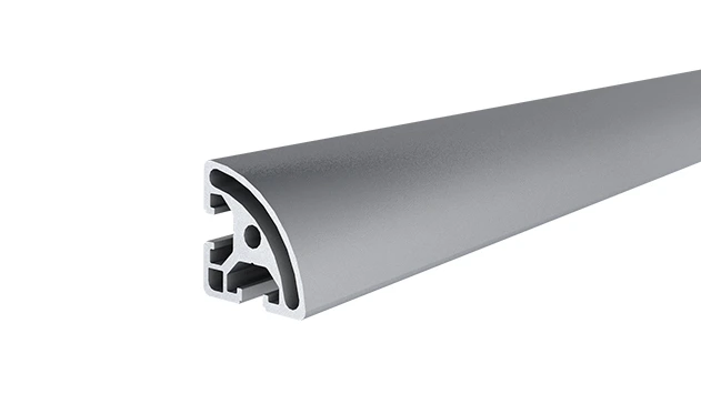
4040R is a 4.00x4.00 CM fractional 40 series square extrusion T-slot profile with two side open T-slots, each side with 4.00cm face,the other side is round face. The profile has align-a-grooves to assist in aligning connecting profiles.
If you've ever walked into a workshop, a manufacturing plant, or even a modern office, chances are you've seen structures built with aluminum profiles—sleek, modular, and surprisingly versatile. From workbenches that hold heavy machinery to material racks that keep production lines organized, these profiles are the unsung heroes of efficient, customizable design. And among the most widely used? The 4040r EU Standard Aluminum Profile. Its popularity isn't just luck; it's the result of a perfect balance between strength, flexibility, and compatibility with a vast range of aluminum profile accessories. But to truly unlock its potential, you need more than just the profile itself—you need precise, well-thought-out technical drawings. That's where CAD (Computer-Aided Design) comes in. In this guide, we'll walk through the ins and outs of creating CAD drawings for 4040r profiles, ensuring your designs are not just functional, but also easy to assemble, cost-effective, and built to last.
Understanding the 4040r EU Standard Aluminum Profile: The Foundation of Your Design
Before diving into CAD software, let's start with the basics: what exactly is the 4040r EU Standard Aluminum Profile, and why does it matter for your drawings? First, the "4040" refers to its cross-sectional dimensions: 40mm in width and 40mm in height. Simple enough. The "r" stands for "rounded," which describes the edges—unlike sharp-edged profiles, the 4040r has gently curved corners, making it safer to handle and easier to integrate with soft materials like rubber gaskets or plastic covers. This small detail might seem minor, but it can drastically affect how you design connections and attachments in CAD.
As an EU standard profile, the 4040r adheres to strict manufacturing norms set by organizations like DIN (Deutsches Institut für Normung) and ISO. This means consistent wall thickness, precise tolerances, and compatibility with EU-standard aluminum extrusion profile accessories across brands. For designers, this standardization is a lifesaver. Imagine spending hours designing a workbench only to find the connectors you ordered don't fit the profile—avoiding that headache starts with understanding the specs.
Pro Tip:
Always verify the specific 4040r variant you're using. While EU standards ensure baseline consistency, some manufacturers offer slight variations (e.g., wall thickness of 1.5mm vs. 2.0mm) based on load-bearing needs. Check the manufacturer's datasheet before finalizing your CAD model—this small step prevents costly rework later.
Key Technical Specifications to Include in Your CAD Drawings
To create accurate CAD drawings, you need to input the 4040r's core dimensions correctly. Let's break them down:
| Parameter | Standard Specification | CAD Input Notes |
|---|---|---|
| Cross-Section Dimensions | 40mm (width) x 40mm (height) | Use exact 40mm x 40mm; avoid rounding (e.g., 40.0mm, not 40.1mm) |
| Wall Thickness | 1.5mm – 2.0mm (varies by load rating) | Check manufacturer datasheet; critical for weight and strength calculations |
| Corner Radius (r) | 2.0mm – 3.0mm (EU standard) | Use fillet tool in CAD with exact radius; affects accessory fit (e.g., end caps) |
| T-Slot Dimensions | Slot width: 8mm; Slot depth: 10mm (typical) | Precision here is key—T-slots are where aluminum profile connectors attach |
| Length Tolerance | ±0.5mm per meter (EU standard) | Account for this in assembly drawings to avoid misalignment |
These specs might look like numbers on a page, but they directly impact your design. For example, the T-slot dimensions determine which aluminum profile accessories will fit—too loose, and connectors will wobble; too tight, and they won't insert at all. When drawing in CAD, take the time to measure these slots accurately. Most CAD software lets you import manufacturer-provided 3D models of the 4040r profile, which is a huge time-saver. If you're drawing from scratch, use calipers to measure a physical sample (if available) and cross-reference with the datasheet.
Setting Up Your CAD Workspace for 4040r Profile Design
Now that you understand the profile's specs, let's talk about setting up your CAD software. Whether you're using AutoCAD, SolidWorks, Fusion 360, or another tool, the goal is to create a workspace that minimizes errors and streamlines your workflow. Here's how to start:
Units and Scale: Stick to Millimeters (mm)
Aluminum profiles, especially EU-standard ones, are designed using the metric system. Set your CAD units to millimeters (mm) from the start. Mixing units (e.g., using inches for some parts and mm for others) is a recipe for disaster. Most software lets you set the default units in the template, so create a 4040r-specific template with mm as the base unit. This way, every new drawing you start will already be in the right scale.
Layers: Organize Like a Pro
Layers are your best friend in CAD. They keep your drawing organized, making it easy to edit, review, and share. For 4040r designs, consider creating these layers:
- Profile Geometry: For the 4040r extrusion itself—this layer should contain only the base profile, no accessories.
- Accessories: For aluminum profile accessories like connectors, end caps, and gussets.
- Dimensions & Annotations: For all measurements, tolerances, and notes (e.g., "Use M8 bolts here").
- Assembly Lines: For showing how parts connect (e.g., dashed lines for hidden connections).
- Load Paths: Optional but useful for structural designs—highlight where weight or stress will be concentrated.
Color-code these layers (e.g., blue for profiles, red for accessories) to visually separate elements. When you need to focus on the profile geometry, you can toggle off the accessories layer; when reviewing annotations, you can hide the load paths. Trust me, your future self (and anyone else reviewing the drawing) will thank you.
Templates: Save Time with Pre-Made 4040r Blocks
If you design with 4040r profiles regularly, create a library of pre-drawn 4040r blocks in your CAD software. A block is a reusable drawing of the profile's cross-section, complete with T-slots, corner radii, and wall thickness. Instead of redrawing the profile every time, you can simply insert the block and stretch it to the desired length. Most manufacturers also offer free 3D models of their 4040r profiles (and accessories) for download—take advantage of these! Importing a manufacturer's 3D model ensures your drawing matches the exact profile they produce, reducing the risk of mismatched parts.

Designing with 4040r Profiles: Key Considerations for CAD Drawings
With your workspace set up, it's time to start designing. But 4040r profiles aren't just rectangles—they're part of a system. Your CAD drawing needs to account for how the profile will interact with accessories, how it will be assembled, and how it will perform in real-world use. Let's dive into the critical design considerations:
Tolerances: The Hidden Detail That Makes or Breaks Assembly
Tolerances are the small allowances in dimensions that account for manufacturing variations. For example, a 4040r profile might have a width tolerance of ±0.2mm, meaning it could be 39.8mm or 40.2mm in reality. If your CAD drawing assumes exactly 40.0mm with no tolerance, you might end up with parts that don't fit. Here's how to handle tolerances:
Profile-to-Accessory Fit: Aluminum profile connectors (like 90° or 45° connectors) are designed to fit the 4040r's T-slots. The slot width is typically 8mm, but the connector's tab might be 7.8mm to allow for easy insertion. In your CAD drawing, show the slot as 8mm and the connector tab as 7.8mm—this 0.2mm gap is intentional and ensures the connector slides in smoothly during assembly.
Stacking Tolerances: If your design uses multiple 4040r profiles (e.g., a workbench with vertical legs and horizontal supports), the total tolerance can add up. For example, if each profile has a length tolerance of ±0.5mm, a bench with four legs could have a total height variation of ±2.0mm. To prevent this from affecting stability, add adjustment features in your design—like slotted holes for feet or leveling pads.
Common Mistake:
Forgetting to include tolerances in CAD drawings. A supplier might deliver a profile that's 0.3mm narrower than your drawing, and suddenly your custom bracket won't fit. Always check the manufacturer's tolerance specs and note them in your annotations (e.g., "Slot width: 8mm ±0.1mm").
Integrating Aluminum Profile Accessories: From Connectors to End Caps
The 4040r's versatility comes from its ability to work with hundreds of aluminum profile accessories. But integrating these into your CAD drawing requires more than just dropping them into place—you need to consider how they attach, how they distribute load, and whether they'll interfere with other parts. Let's take a closer look at a few common accessories and how to draw them:
90° Aluminum Profile Connectors: The Backbone of Right-Angle Joints
90° connectors are used to join two 4040r profiles at a right angle (e.g., a vertical leg and a horizontal beam in a workbench). There are two main types: internal (fits inside the profile) and external (clamps around the outside). For internal connectors, your CAD drawing must show the connector's tabs inserting into the T-slots. Measure the connector's length—most are 30mm to 50mm long—and ensure it doesn't extend beyond the profile's end unless intentional. For external connectors, show the clamp wrapping around the profile's corners, leaving enough space for bolts (typically M6 or M8) to tighten without hitting other parts.
End Caps: Finishing Touches with a Purpose
End caps might seem like a minor detail, but they prevent debris from getting into the profile's T-slots and protect workers from sharp edges (even though the 4040r has rounded edges, the cut ends can still be rough). In CAD, draw the end cap as a solid block that fits snugly into the profile's cross-section. Most end caps have a lip that overlaps the profile by 1-2mm—include this in your drawing to ensure a tight fit. If the end cap has a hole (for cables, for example), note the hole diameter and position relative to the T-slots.
Gussets: Adding Strength Where It Matters
Gussets are triangular plates used to reinforce joints (e.g., where a horizontal beam meets a vertical leg). They distribute stress and prevent the joint from bending under load. When drawing gussets in CAD, pay attention to their thickness (usually 2mm to 5mm, depending on load) and how they attach to the profile. Most gussets use T-slot nuts and bolts, so align their mounting holes with the 4040r's T-slots. Avoid making gussets too large—they should reinforce the joint without adding unnecessary weight or blocking access to other parts.
Creating Assembly Drawings: Making It Easy for the Shop Floor
A great CAD drawing isn't just for designers—it's for the people who will actually build the structure. Assembly drawings bridge the gap between design and construction, showing step-by-step how the 4040r profiles and accessories come together. Here's how to make them clear and user-friendly:
Exploded Views: See How Parts Fit Before Assembly
Exploded views are a game-changer. They show each part separated by a small distance, with lines connecting them to their final position. For a 4040r workbench, an exploded view might show the vertical legs, horizontal beams, connectors, and end caps all spaced apart, making it easy to see which part goes where. Use different line styles (e.g., solid lines for visible parts, dashed lines for hidden parts) and label each component with a part number (e.g., "A: 4040r Profile, 1000mm").
Bill of Materials (BOM): No More Guesswork
Include a BOM directly in your CAD drawing or as a separate table. The BOM lists every part needed, including:
- Part number (from the manufacturer, if available)
- Description (e.g., "4040r EU Standard Aluminum Profile, 1.5mm wall thickness")
- Quantity (how many of each part you need)
- Material (e.g., "6063-T5 Aluminum")
- Supplier (optional but helpful for procurement teams)
Link each BOM item to the exploded view using balloons (small circles with numbers that correspond to the BOM list). This way, anyone assembling the structure can match the part in the drawing to the BOM entry in seconds.
Assembly Sequences: Step-by-Step Instructions
For complex designs (e.g., a multi-level material rack), break the assembly into steps. Use numbered callouts (e.g., "Step 1: Attach 90° connectors to vertical legs") and include close-up views of tricky joints. For example, if a connector requires a specific torque (e.g., "Tighten M8 bolts to 25 Nm"), note that in the step. The goal is to make the assembly process so clear that even someone new to 4040r profiles can follow along.
Common Pitfalls to Avoid in 4040r CAD Drawings
Even experienced designers make mistakes with 4040r profiles. Here are the most common ones and how to steer clear:
Ignoring T-Slot Alignment
The T-slots in 4040r profiles are spaced at specific intervals (usually 20mm or 40mm apart). If your CAD drawing places a connector's mounting hole halfway between two T-slots, the connector won't attach—simple as that. Always align accessory holes with the T-slots. Most manufacturers provide T-slot spacing diagrams in their datasheets—keep one open while designing.
Overlooking Material Thickness for Cutouts
If you need to cut a notch or hole in the 4040r profile (e.g., to run cables through), remember the wall thickness. Cutting too deep can weaken the profile or make it impossible to attach accessories nearby. For example, a 1.5mm wall profile has only 1.5mm of material between the T-slot and the outside edge—cutting a 2mm notch here would punch through the wall entirely. Use section views in CAD to check cutout depths before finalizing.
Forgetting Clearance for Tools
Even if two parts fit perfectly on paper, they might be impossible to assemble if there's no space for a wrench or screwdriver. For example, if two connectors are placed 10mm apart on a profile, you might not be able to fit a socket wrench between them to tighten the bolts. In CAD, simulate the assembly process mentally: visualize holding a tool and ask, "Can I reach this bolt?" If not, adjust the spacing.
Best Practices: Taking Your 4040r CAD Drawings to the Next Level
Now that you know what to avoid, let's focus on best practices that will make your drawings stand out:
Use 3D Modeling for Complex Assemblies
2D drawings are great for simple designs, but 3D modeling (in tools like SolidWorks or Fusion 360) is better for complex assemblies. 3D models let you rotate the design, check for collisions (e.g., a connector hitting a gusset), and even run stress tests to ensure the structure can handle the intended load. Many 3D software tools also generate 2D drawings automatically from the 3D model, saving you time.
Collaborate with Suppliers Early
Your aluminum profile supplier isn't just a vendor—they're a resource. Share your CAD drawing with them before finalizing. They can spot issues you might have missed, like a discontinued accessory or a better connector for your design. Some suppliers even offer free design reviews—take advantage of that expertise.
Document Everything
Annotations aren't optional. Every critical detail should be noted: tolerances, bolt sizes, torque values, material grades, and even assembly tips (e.g., "Hand-tighten first, then torque"). The goal is to make the drawing so clear that someone with no prior experience can build the structure correctly.
Case Study: Designing a 4040r Workbench with CAD
To put all this into context, let's walk through a real-world example: designing a simple workbench using 4040r profiles, aluminum profile accessories, and CAD. The workbench needs to be 1200mm long, 600mm deep, and 800mm high, with a wooden top and casters for mobility.
Step 1: Define the Structure
The frame will use four vertical 4040r legs (800mm long), two horizontal front/back beams (1200mm long), and two horizontal side beams (600mm long). The legs will connect to the beams using 90° aluminum profile connectors. Casters will attach to the bottom of the legs, and the wooden top will sit on top of the beams.
Step 2: Draw the Profile Geometry
In CAD, create a new drawing using the 4040r template (mm units, layers set up). Draw the four legs as vertical rectangles (40mm x 40mm x 800mm), then add the front/back and side beams. Ensure the beams are centered on the legs for balance.
Step 3: Add Accessories
insert 90° connectors at each leg-beam joint (8 connectors total). Align their mounting holes with the T-slots in the 4040r profiles. Add end caps to the top of the legs (to protect the wooden top from scratches) and casters to the bottom (using caster mounting plates that attach via T-slots).
Step 4: Dimension and Annotate
Add dimensions for all profile lengths, connector positions, and caster spacing. Note the caster type (e.g., "Locking casters, 50mm diameter") and the wood top thickness (e.g., "25mm plywood, screwed to beams via T-slot nuts").
Step 5: Create an Exploded View and BOM
Generate an exploded view showing all parts, then create a BOM listing the 4040r profiles, connectors, end caps, casters, and wood top. Include part numbers from the supplier to make ordering easy.
The final drawing is clear, annotated, and assembly-ready. When the shop floor team builds it, they'll have no trouble following the steps—and the workbench will be strong, stable, and exactly as designed.
Conclusion: Mastering 4040r CAD Drawings for Better Designs
Designing with 4040r EU Standard Aluminum Profiles is all about precision, creativity, and attention to detail. By understanding the profile's specs, setting up your CAD workspace effectively, integrating accessories thoughtfully, and avoiding common mistakes, you can create technical drawings that bring your ideas to life—on time and on budget. Remember, the best CAD drawings aren't just about lines and dimensions; they're about communication. They speak to the assembler, the supplier, and anyone else who interacts with your design, ensuring everyone is on the same page.
So the next time you fire up your CAD software to design a workbench, material rack, or any other 4040r structure, take a moment to apply these guidelines. Your future self (and the shop floor team) will thank you. And who knows? With practice, you might just become the go-to expert for 4040r profile designs in your workplace. Happy drawing!