- Company Articles
- Products and Technology
- Product knowledge
- CAD Design Tips for Three Way Lean Pipe Joint Systems

CAD Design Tips for Three Way Lean Pipe Joint Systems
Related Product
Three Way Lean Pipe Joint
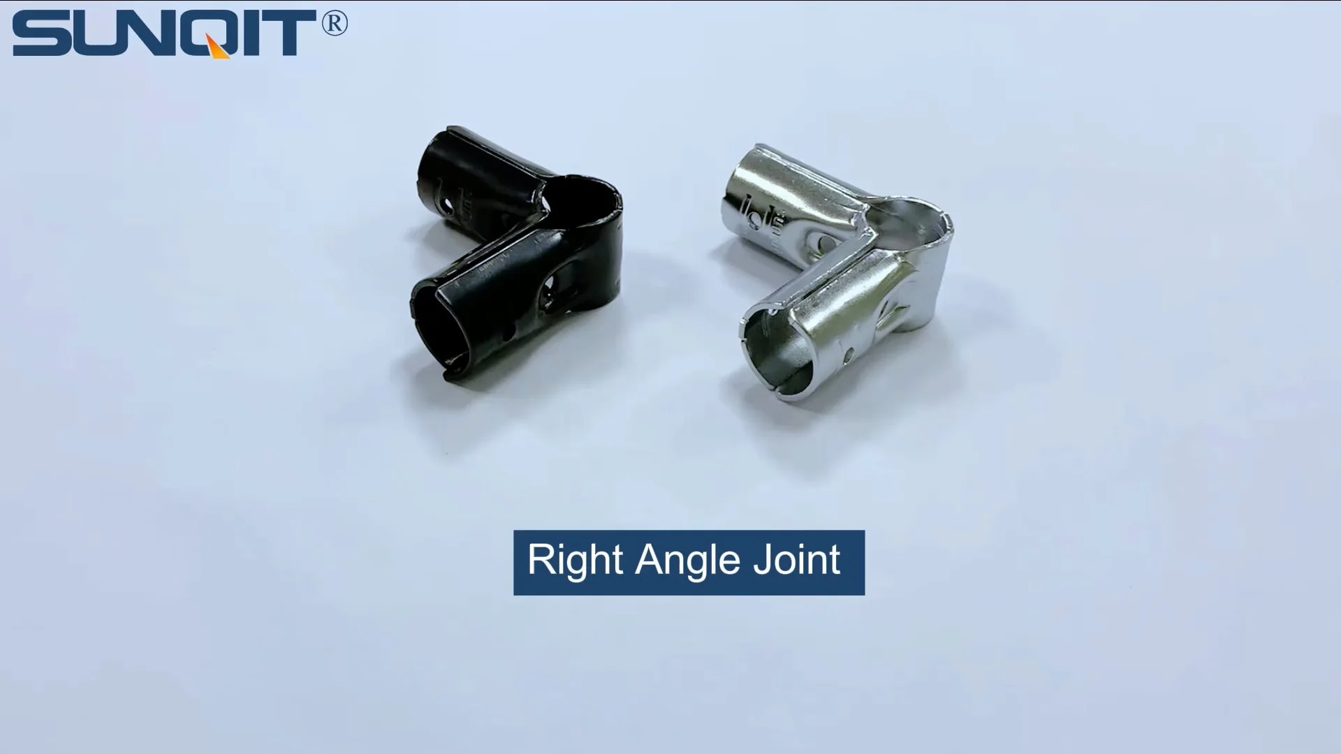
Three way lean pipe joint for 3 pcs 28MM lean pipe connection in straight angle, which used widely in workbench, flow rack, hand trolley frame connection.
If you've ever stood in a manufacturing facility and marveled at how seamlessly workbenches, flow racks, and material trolleys come together to keep production moving, you've witnessed the power of lean pipe systems. These modular setups—built from pipes, joints, and accessories—are the unsung heroes of efficient workflows, adapting to everything from electronics assembly lines to warehouse picking stations. But here's the thing: behind that seamless functionality lies hours of careful design, and at the heart of it all are the connectors that hold everything together. Enter the three way lean pipe joint—a small but mighty component that can make or break your system's stability, flexibility, and overall performance.
Designing with three way lean pipe joints in CAD (Computer-Aided Design) is where the magic starts. It's where abstract ideas about workflow efficiency turn into precise measurements, 3D models, and actionable blueprints. But if you've ever spent hours perfecting a CAD model only to realize the joints don't align with the pipes, or the load capacity is miscalculated, you know how frustrating the process can be. Missteps in CAD lead to rework, wasted materials, and delayed production—exactly what lean systems aim to eliminate.
That's why we've put together this guide. Whether you're a seasoned CAD designer new to lean systems or a manufacturing engineer tasked with optimizing your facility's layout, these tips will help you navigate the unique challenges of designing with three way lean pipe joints. We'll cover everything from pre-design prep to advanced CAD tricks, with real-world examples and common pitfalls to avoid. By the end, you'll be able to create models that translate flawlessly from screen to shop floor—saving time, reducing errors, and building lean systems that truly deliver on efficiency.
1. Understanding Three Way Lean Pipe Joints: More Than Just a Connector
Before diving into CAD, let's start with the basics: what exactly is a three way lean pipe joint, and why does it matter so much? At its core, a three way joint is a modular connector designed to join three pipes at specific angles (usually 90°, 45°, or custom angles) in a lean system. Unlike fixed welds or rigid brackets, these joints allow for quick assembly, disassembly, and reconfiguration—key features for adapting to changing production needs. But not all three way joints are created equal, and understanding their nuances is critical to successful CAD design.
1.1 Materials and Load Capacity: The Foundation of Durability
Three way lean pipe joints come in a range of materials, each with its own strengths and limitations. The most common options include:
- Chrome-Plated Steel: A workhorse in industrial settings, chrome-plated steel joints offer high strength (often supporting loads up to 200kg per joint) and resistance to wear and tear. They're ideal for heavy-duty applications like material racks or workbenches supporting bulky equipment. However, they add weight to the system, which can be a consideration for mobile trolleys.
- Aluminum: Lightweight and corrosion-resistant, aluminum joints are perfect for cleanrooms, food processing facilities, or applications where weight matters (think turnover trolleys). They're also easier to handle during assembly, though their load capacity is generally lower than steel (around 100–150kg per joint).
- Plastic-Coated Steel: Combining steel's strength with a plastic coating (often PVC or nylon), these joints reduce noise, prevent scratches on sensitive parts (like electronics components), and add a non-slip grip. They're popular in assembly lines where product protection is key.
In CAD, material choice directly impacts your model's accuracy. For example, if you're designing a workbench that needs to support 300kg of equipment, specifying a plastic-coated steel joint with a 200kg load capacity will lead to failure. CAD models must reflect real-world material limits, so always cross-reference the joint manufacturer's specs (we'll cover where to find these later) before finalizing your design.
1.2 Fixed vs. Swivel: Flexibility vs. Stability
Three way joints also come in fixed and swivel (rotary) variants, and choosing the right type depends on how your system will be used. Fixed joints lock pipes into a set angle (e.g., three pipes meeting at 90°), making them ideal for rigid structures like workbench frames or stationary material racks. Swivel joints, on the other hand, allow one or more pipes to rotate, enabling adjustable components like tilting shelves or movable tool holders.
In CAD, this distinction affects how you model movement and interference. A swivel joint, for instance, requires you to account for rotation range (e.g., 180° swivel) and ensure nearby components (like a roller track) don't block motion. Fixed joints, by contrast, demand precise angle alignment to avoid stress on the pipes—even a 5° misalignment can lead to uneven load distribution and premature wear.
1.3 Compatibility: Not All Pipes Play Nice Together
A three way joint is only as good as the pipes it connects. Most joints are designed for specific pipe diameters (common sizes include 28mm, 30mm, and 40mm) and materials (steel, aluminum, or plastic-coated steel). Using a 28mm joint with a 30mm aluminum pipe, for example, will result in a loose fit that compromises stability. In CAD, this means you can't just "eye" the pipe diameter—you need to input exact measurements and verify compatibility with the joint's inner diameter and grip mechanism (e.g., set screws, spring-loaded clips).
Pro tip: Many manufacturers provide CAD libraries or 3D models of their joints and pipes (we'll talk more about this in Section 3). Using these pre-made assets ensures compatibility and saves you from modeling every thread, groove, or clip from scratch.
2. Pre-Design Prep: Gather Your Specs Before Opening CAD
You wouldn't build a house without a blueprint, and you shouldn't design a lean system without first gathering the right specs. Pre-design preparation is where you lay the groundwork for a smooth CAD process, avoiding last-minute scrambles to find missing dimensions or load ratings. Here's what you need to collect:
2.1 Joint Specifications: The Devil's in the Details
Start by obtaining the manufacturer's datasheet for your chosen three way lean pipe joint. This document is gold—it contains critical info like:
- Overall dimensions (length, width, height)
- Inner diameter (to match pipe size)
- Material thickness and weight
- Load capacity (static and dynamic—dynamic is key for moving trolleys!)
- Mounting options (e.g., set screws, holes for bolts, or snap-fit mechanisms)
- Operating temperature range (important for extreme environments)
If you're using a custom or less common joint, you may need to reverse-engineer the specs by measuring a physical sample with calipers. Just be sure to account for manufacturing tolerances (usually ±0.1mm to ±0.5mm for metal joints) to avoid over-constraining your CAD model.
2.2 System Requirements: What Will Your Lean System Actually Do?
Next, define the purpose of your lean system. Is it a workbench for assembly? A flow rack for material handling? A turnover trolley for transporting parts? Each use case imposes unique demands on the three way joints. For example:
- Workbench: Needs to support static loads (tools, components, workers) and may require integrated features like drawers or roller tracks. Joints here need high vertical load capacity.
- Flow Rack: Features inclined roller tracks where gravity moves materials. Joints must handle lateral forces from sliding items and maintain precise angles to ensure smooth flow.
- Turnover Trolley: Moves on casters, so joints must withstand dynamic loads (vibration, sudden stops) and uneven weight distribution when the trolley is in motion.
Write down these requirements in detail. For example: "Workbench E (single deck, without caster) must support 200kg evenly distributed across a 1200mm x 800mm surface, with a 45° aluminum guide rail A along one edge for component bins." The more specific you are, the easier it will be to translate these into CAD constraints.
2.3 Component Compatibility: Map Out the Entire Ecosystem
Three way joints rarely work alone. They connect to pipes, which connect to other joints, which connect to accessories like casters, roller tracks, or workbench surfaces. A single compatibility issue—like a joint that blocks the mounting hole for a caster accessory—can derail your entire design. To avoid this, create a "component map" listing every part that will interact with your three way joints, including:
- Pipes (material, diameter, length)
- Accessories (casters, levelers, roller track guide rails, e.g., plastic roller track guide rail yellow or grey)
- Work surfaces (aluminum honeycomb panels, wooden tops, etc.)
- Secondary joints (two way, four way, swivel joints)
For example, if you're designing a flow rack with "material rack B (3 row and 3 floor)," you'll need to ensure the three way joints connecting the vertical supports to the horizontal roller tracks are compatible with both the rack's pipes and the roller track's mounting brackets (like roller track placon mount for aluminum profile flat). A quick check here saves hours of rework later.
2.4 Create a Spec Table: Your Quick-Reference Guide
With all your specs gathered, organize them into a table for easy access during CAD design. Here's an example for common three way lean pipe joints:
| Joint Type | Material | Compatible Pipe Diameter (mm) | Max Static Load (kg) | Mounting Mechanism | CAD Model Availability |
|---|---|---|---|---|---|
| 90° Fixed Chrome-Plated Steel Joint | Steel, chrome-plated | 28 | 300 | 2 set screws (M6) | Yes (STEP file) |
| 135° Aluminum Swivel Joint | Aluminum alloy | 30 | 150 | Spring-loaded clip + set screw | Yes (SolidWorks part) |
| Plastic-Coated Steel 45° Joint | Steel, PE-coated | 40 | 200 | External cam lever | No (need to model) |
Keep this table open while designing—you'll refer to it constantly to ensure your model aligns with real-world specs.

3. CAD Software Setup: Tailor Your Workspace for Lean Systems
Now that you've done your prep work, it's time to set up your CAD software for success. Lean pipe systems have unique needs—modularity, repetitive components, and precise angle alignments—that standard CAD templates don't always address. By customizing your workspace, you'll work faster and reduce errors. Here's how:
3.1 Create a Lean System Template
Most CAD software (AutoCAD, SolidWorks, Fusion 360, etc.) allows you to save custom templates with predefined settings. Create one specifically for lean pipe systems with the following:
- Layers: Organize by component type: Pipes, Joints, Accessories (Casters, Roller Tracks), Work Surfaces, Annotations. This makes it easy to hide/show parts and avoid clutter.
- Units: Use metric (mm) for consistency with most lean pipe manufacturers. Set precision to 0.01mm for critical dimensions (joint holes, pipe diameters) and 1mm for less critical ones (overall system length).
- Dimension Styles: Customize text size, arrowheads, and tolerances to match your company's standards. For lean systems, include tolerance notations like "±0.5mm" for pipe lengths to account for cutting variations.
- Grid and Snap: Set grid spacing to match common pipe increments (e.g., 50mm or 100mm) and enable snap-to-grid for quick alignment of joints and pipes.
Pro tip: Save this template as "Lean System Template" so you can start every new project with a consistent setup.
3.2 Build a Library of Custom Blocks (2D) or Components (3D)
Three way joints, pipes, and accessories are repetitive in lean systems—you'll use the same components across multiple designs. Instead of modeling them from scratch each time, build a library of custom blocks (in 2D) or parametric components (in 3D). For example:
- 3D Components: Import manufacturer-provided STEP files for three way joints, or model your own using the specs from Section 2. Add parameters like "PipeDiameter" or "JointAngle" so you can quickly adjust the component for different projects.
- 2D Blocks: Create symbols for joints, pipes, and roller tracks (e.g., a circle with three lines for a three way joint) to use in 2D layouts. Include attributes like "Model Number" or "Load Capacity" that you can edit for each instance.
Most CAD software lets you save these libraries locally or on a shared server, so your entire team can access them. Over time, your library will grow to include rare components like "stainless steel swivel roller balls 1 inch" or "internal rotatary aluminum joint," making even complex designs faster to complete.
3.3 Set Up Assembly Constraints for Modular Design
In 3D CAD, assemblies are where your lean system comes to life. To ensure joints and pipes behave like they would in the real world, use assembly constraints (mates, joints, or constraints, depending on your software) to define how parts interact. For three way lean pipe joints, critical constraints include:
- Coincident Mates: Align the center axis of a pipe with the center axis of a joint socket to ensure perfect alignment.
- Angle Mates: Set the angle between two pipes connected by a three way joint (e.g., 90° for vertical and horizontal pipes).
- Distance Mates: Fix the position of a joint along a pipe (e.g., "100mm from the end of the pipe" for a shelf support).
- Rigid Groups: Group joints and pipes that shouldn't move relative to each other (e.g., the frame of a workbench) to simplify assembly navigation.
Avoid over-constraining your assembly—too many constraints can make it hard to adjust the design later. For example, if you set both a coincident mate and a distance mate between a joint and a pipe, changing the pipe length will cause a conflict. Stick to the minimum constraints needed to define the relationship.

4. 3D Modeling Best Practices: From Pipes to Perfect Joints
Now it's time to start modeling. Whether you're using SolidWorks, Fusion 360, or AutoCAD 3D, these best practices will help you create accurate, functional models of three way lean pipe joints and their surrounding systems.
4.1 Start with a Skeleton Sketch: Define the System's "Backbone"
Before adding joints or pipes, sketch the overall layout of your lean system. In 3D CAD, this is often called a "skeleton" or "layout sketch." It defines the system's key dimensions, angles, and load-bearing points—acting as a guide for placing joints and pipes. For example, if you're designing a workbench, your skeleton sketch might include:
- A rectangle representing the work surface (1200mm x 800mm)
- Vertical lines at each corner for the leg pipes (height: 850mm)
- Horizontal lines for the lower shelf supports (600mm from the floor)
- Angled lines for roller track guides (10° incline for gravity flow)
Use construction lines (non-printable, dashed lines) for this sketch so they don't interfere with the final model. The skeleton ensures all components align with the system's intended dimensions, preventing joints from being placed too close together or pipes from being too short.
4.2 Model Pipes as Extrusions with Realistic Thickness
Pipes are the "bones" of your lean system, and their structural integrity depends on material thickness. Don't model pipes as solid cylinders—instead, use extruded (thin-walled) cylinders to mimic real-world pipes. For example:
- A 28mm diameter steel pipe with 1.5mm wall thickness (common in lean systems) should be modeled as a cylinder with outer diameter 28mm and inner diameter 25mm (28mm – 2*1.5mm).
- Aluminum pipes, often lighter, might have a 1.2mm wall thickness for the same outer diameter.
Why does this matter? Because wall thickness affects weight, load capacity, and how the pipe fits into the joint. A joint designed for a 1.5mm wall pipe may not grip a 1.2mm wall pipe securely, leading to slippage. By modeling accurate wall thickness, you can run stress analyses later to ensure the pipes won't bend or buckle under load.
4.3 Detail the Joint: Don't Ignore the Small Features
Three way joints have small but critical features: set screws, spring clips, grooves for pipes, and mounting holes. These details might seem minor, but they can cause major issues if omitted. For example, a set screw hole that's too small won't allow the screw to tighten, leaving the pipe loose. In CAD, take the time to model these features accurately:
- Set Screws: Include the threaded hole (e.g., M6 x 1.0mm thread) and the screw itself (countersunk or hex head) to check clearance with surrounding pipes.
- Grooves: If the joint has a groove to accept a pipe's lip, model the groove's depth and width to match the pipe's profile.
- Mounting Holes: For joints that attach to work surfaces or accessories, include holes with correct diameter and spacing (e.g., 6mm diameter holes on a 50mm bolt circle).
If you're short on time, use manufacturer-provided 3D models—most suppliers offer STEP or IGES files that include these details. Just verify the model matches the specs in your datasheet (some older models might not reflect design updates).
4.4 Use Assembly Features to Simulate Real-World Connections
In 3D CAD assemblies, use features like "mate references" or "joints" to simulate how the three way joint connects to pipes. For example:
- Concentric Mate: Align the pipe's outer diameter with the joint's inner socket to ensure centering.
- Distance Mate: Set the pipe to extend 10mm into the joint (a common insertion depth) to ensure a secure fit.
- Threaded Mate: For set screws, simulate the screw tightening against the pipe to check for proper grip (the screw should indent slightly into the pipe's surface).
These features not only ensure accurate placement but also let you "test" the assembly in CAD. For example, you can drag a pipe to see if it moves freely in a swivel joint or if the set screw prevents rotation in a fixed joint.

5. Tolerance and Fit: The Hidden Key to Assembly Success
In manufacturing, "close enough" rarely is—especially with lean pipe systems. Tolerances (the allowable variation in dimensions) and fit (how tightly parts assemble) determine whether your CAD model translates into a system that's easy to build and performs reliably. Three way joints are particularly sensitive here: too loose, and the system wobbles; too tight, and assembly becomes a struggle. Here's how to manage tolerances and fit in CAD:
5.1 Understand Clearance vs. Interference Fits
Joints and pipes use either clearance fits (parts have space between them) or interference fits (parts press together). In lean systems, most three way joints use clearance fits with a locking mechanism (set screws, clips) to secure the pipe. For example:
- A 28mm pipe with a 28.5mm joint socket has a 0.5mm clearance fit—enough space to insert the pipe easily, then tightened with a set screw.
- Too much clearance (e.g., 1mm) means the pipe wobbles before tightening; too little (e.g., 0.1mm) makes insertion difficult, especially if the pipe is slightly bent.
In CAD, specify these clearances using dimension tolerances. For the pipe-joint fit, write the joint socket diameter as "28.5mm +0.1/-0mm" and the pipe outer diameter as "28mm ±0.2mm." This ensures the maximum clearance is 28.5mm – 27.8mm = 0.7mm (still manageable) and the minimum is 28.4mm – 28.2mm = 0.2mm (tight but insertable).
5.2 Account for Thermal Expansion (Yes, Even in Lean Systems)
It might seem overkill, but temperature changes can affect lean systems—especially those in factories with heat-generating equipment or outdoor warehouses. Metal pipes and joints expand when heated and contract when cooled, which can loosen joints or bow pipes over time. For example, a steel pipe that's 1000mm long at 20°C will expand by ~0.12mm when heated to 40°C (using steel's thermal expansion coefficient of 12 x 10^-6 per °C). That's a small change, but over a long system with many joints, it adds up.
To address this in CAD, add small gaps (e.g., 0.5mm) between fixed joints in long horizontal runs. For example, in a 3-meter flow rack with multiple three way joints, space the joints 0.5mm apart to allow for expansion without bowing the pipe.
5.3 Test Fit with a "Digital Mockup"
Before finalizing your design, run a "digital mockup" in CAD to test how all components fit together. This involves assembling the entire system (pipes, joints, accessories) and checking for:
- Interferences: Parts that overlap or collide (e.g., a joint blocking a caster wheel's rotation).
- Undersized Gaps: Spaces too small for tools (e.g., a wrench can't reach a set screw because another joint is in the way).
- Over-Constrained Assemblies: Parts that can't move as intended (e.g., a swivel joint that hits a pipe when rotated).
Most 3D CAD software has built-in interference detection tools—use them! For example, SolidWorks' "Interference Detection" feature highlights overlapping components in red, making it easy to spot issues. Fixing these in CAD is far cheaper than discovering them during assembly.
6. Case Study: Designing a Flow Rack with Three Way Aluminum Joints
The Challenge
A electronics manufacturer needed a flow rack for printed circuit board (PCB) assemblies. The requirements: 3 rows x 3 floors (Material Rack B), 1200mm wide x 600mm deep x 1500mm tall, with 1-inch swivel roller balls on each shelf for smooth PCB movement. The system had to be lightweight (to allow repositioning) but sturdy enough to hold 50kg per shelf. They chose aluminum pipes (30mm diameter, 1.2mm wall) and aluminum three way joints for corrosion resistance and weight savings.
The CAD Design Process (with Tips Applied)
Step 1: Pre-Design Prep – Gathered specs for the aluminum three way joints: material (6063 aluminum alloy), max load 150kg, compatible with 30mm pipes, and STEP files available from the supplier. Created a component map including pipes, joints, swivel roller balls, and aluminum guide rail B for shelf edges.
Step 2: Skeleton Sketch – Drew the flow rack outline: 3 vertical columns (1500mm tall), 3 horizontal shelves per column (spaced 500mm apart), and 10° inclined lines for the roller tracks to ensure gravity flow.
Step 3: Assembly with Mates – Used concentric mates to align pipes with joint sockets and distance mates to set pipe insertion depth (15mm into each joint). Added angle mates to set the roller tracks at 10°, critical for PCB flow.
Step 4: Tolerance Check – Specified joint socket diameter as 30.5mm +0.1/-0mm and pipe outer diameter as 30mm ±0.2mm to ensure clearance fit. Added 0.5mm gaps between horizontal pipes and vertical joints to account for thermal expansion.
Step 5: Interference Detection – Ran a digital mockup and discovered the swivel roller balls (1 inch diameter) were too close to the vertical joints, blocking PCB movement. Adjusted the shelf width to move the joints outward by 20mm, solving the issue.
The Result
The flow rack assembled on the first try, with no rework needed. The aluminum joints and pipes kept the system lightweight (total weight 75kg), and the roller tracks moved PCBs smoothly without jamming. The manufacturer reported a 20% reduction in material handling time and zero complaints about assembly difficulty—all thanks to careful CAD design.
7. Common Pitfalls to Avoid: Lessons from the Shop Floor
Even with careful planning, CAD designs for three way lean pipe joints can go wrong. Here are the most common mistakes we've seen—and how to steer clear of them:
7.1 Ignoring Pipe Deflection Under Load
Pipes aren't rigid—they bend under load, especially long horizontal runs. For example, a 1200mm long aluminum pipe with a 1.2mm wall thickness will deflect (bend) ~5mm under a 50kg load. If you don't account for this in CAD, the deflected pipe might sag into a roller track or cause joints to lean, leading to uneven weight distribution.
Fix: Use CAD's simulation tools to run a simple stress analysis. Apply the expected load to horizontal pipes and check deflection. If it's excessive (more than 10mm for a workbench), add intermediate support joints or switch to a thicker-walled pipe.
7.2 Using Outdated or Generic Joint Models
Relying on old CAD models or generic "three way joint" blocks from the internet is a recipe for disaster. Manufacturers often update joint designs (e.g., adding a second set screw for better grip), and generic models rarely include critical details like thread size or socket depth.
Fix: Always download the latest CAD models from your joint supplier's website. If none are available, measure a physical joint with calipers and model it from scratch, cross-referencing the datasheet for specs.
7.3 Overlooking Accessibility for Assembly and Maintenance
It's easy to focus on the final design and forget about how the system will be built or repaired. For example, a three way joint placed too close to a roller track might make it impossible to tighten the set screw with a wrench. Or a joint under a workbench shelf might be hard to reach if a component needs replacement.
Fix: In CAD, add "clearance zones" around joints—areas 50mm x 50mm where no other components are allowed. This ensures tools can reach set screws and joints can be accessed for reconfiguration.
7.4 Underestimating the Weight of Accessories
Joints must support not just pipes and work surfaces, but also accessories like casters, drawers, and tool holders. A common mistake is calculating load capacity based only on the main pipes, forgetting that a heavy caster (e.g., a 10kg heavy-duty caster) adds stress to the joint it's mounted on.
Fix: Create a "weight budget" for each joint, adding up the weight of pipes, accessories, and intended loads. For example, a corner joint on a trolley might support: 2kg (pipe) + 10kg (caster) + 50kg (dynamic load) = 62kg. Ensure this is below the joint's max load rating (e.g., 150kg for aluminum joints).
8. Advanced Tips: Taking Your CAD Design to the Next Level
Once you've mastered the basics, these advanced tips will help you design lean systems that are not just functional, but optimized for efficiency, cost, and scalability.
8.1 Use Parametric Design for Easy Reconfiguration
Parametric CAD tools (like Fusion 360 or SolidWorks) let you define relationships between components—change one dimension, and the rest update automatically. For lean systems, this is a game-changer. For example, create a parametric workbench model where:
- Changing "WorkbenchLength" from 1200mm to 1500mm automatically adjusts pipe lengths, joint positions, and shelf dimensions.
- Swapping "CasterType" from "Fixed" to "Swivel" updates the joint and caster mounting holes.
To set this up, use variables (parameters) for key dimensions and equations to define relationships (e.g., "ShelfWidth = WorkbenchLength – 100mm"). This saves hours when reconfiguring systems for different departments or products.
8.2 Run Stress Analyses to Validate Load Capacity
Most CAD software includes basic stress analysis tools (e.g., SolidWorks Simulation, Fusion 360 Simulation) that let you test how joints and pipes perform under load. For example, you can apply a 200kg load to a workbench surface and check if the three way joints or pipes experience excessive stress (measured in MPa, or megapascals).
Aim for a safety factor of at least 2—meaning the calculated stress should be half the material's yield strength (e.g., aluminum alloy 6063 has a yield strength of ~200MPa, so keep stress below 100MPa). If stress is too high, thicken the pipe walls, add more joints, or switch to a stronger joint material.
8.3 Collaborate with Shop Floor Teams Early
Your CAD model might look perfect on screen, but shop floor teams—who actually assemble the systems—have invaluable insights. They know which joints are hard to tighten, which pipe lengths are tricky to cut, and which accessories often fail in real use.
Share your CAD model with assembly technicians early in the design process. Ask for feedback like: "Is there enough space to use a wrench on this joint?" or "Do we have the tools to cut pipes to this length?" Their input will save you from redesigning after the first prototype.
Conclusion: From CAD Model to Lean Success
Designing with three way lean pipe joints in CAD is a blend of art and science. It requires technical precision to model joints and pipes accurately, but also a deep understanding of how the system will be used—by workers, with tools, in real-world environments. By following these tips—from pre-design prep to advanced stress analysis—you'll create models that are not just drawings, but blueprints for efficient, adaptable, and durable lean systems.
Remember, the goal of lean manufacturing is to eliminate waste—and that starts with waste in the design process. A well-designed CAD model reduces rework, minimizes material waste, and ensures your lean system delivers on its promise of efficiency from day one. So the next time you fire up your CAD software, start with the specs, build a solid skeleton, and don't forget to test that joint fit. Your shop floor team (and your bottom line) will thank you.
Now go out there and design something amazing. The world of lean manufacturing is waiting for your next innovation—and it all starts with a well-designed three way joint.