- Company Articles
- Products and Technology
- Product knowledge
- CAD Modeling Tips for 3060 National Standard Profile A Structures

CAD Modeling Tips for 3060 National Standard Profile A Structures
Related Product
3060 National Standard Profile A
Workbench, production line, logistic rack, warehouse rack Industry: Manufacturer workshop, Automobile, Electronic, Assembling, logistic
In the world of industrial design and manufacturing, few components are as versatile and indispensable as the 3060 national standard profile A. This aluminum extrusion has become a cornerstone of modern workbenches, material racks, and lean system setups, thanks to its perfect balance of strength, lightweight construction, and adaptability. But even the most reliable profile can fall short if its CAD model isn't crafted with precision and foresight. Whether you're designing a simple workbench or a complex assembly line, the difference between a smooth build and a frustrating, error-ridden process often lies in the details of your CAD modeling. Let's dive into actionable tips that will elevate your 3060 profile designs, ensuring they're not just technically accurate but also practical, efficient, and ready for real-world use.
1. Start with a Deep Dive into Profile Specifications
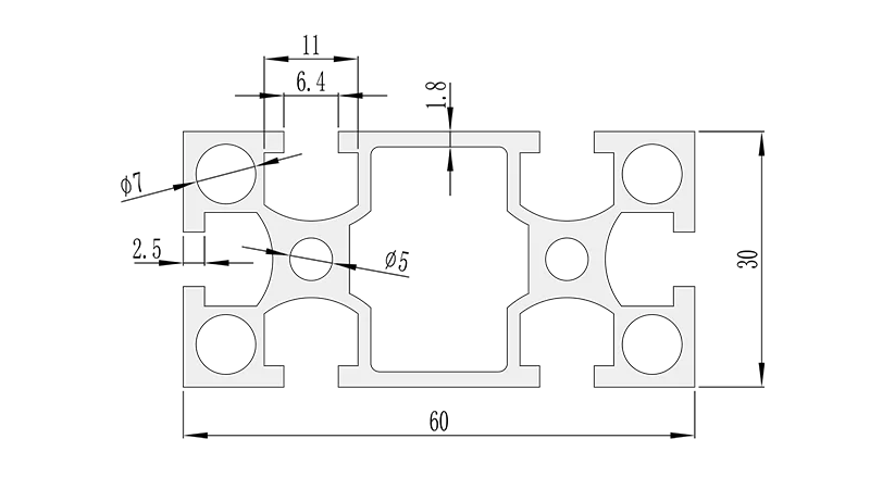
Before you even open your CAD software, take time to get intimately familiar with the 3060 national standard profile A's specs. This isn't just about knowing it's a 30mm x 60mm extrusion—though that's the starting point. Dig into the details: the shape of the T-slots (width, depth, and placement), wall thickness, corner radii, and any unique features like chamfers or reinforcement ribs. These nuances might seem minor, but they directly impact how aluminum profile accessories (like brackets, connectors, and panels) attach and function.
For example, the T-slots on the 3060 profile are typically designed to accept M6 or M8 bolts, but the exact slot width (often 8mm or 10mm) varies by manufacturer. If your CAD model assumes a 10mm slot but the actual profile uses 8mm, your carefully designed bracket might not fit, leading to last-minute redesigns or costly part replacements. Most suppliers provide detailed 2D drawings or 3D models of their profiles—download these and use them as a base instead of creating a profile from scratch. This not only saves time but also ensures your model aligns with real-world tolerances.
Another key spec to note is the profile's weight capacity. The 3060 profile A is robust, but its load-bearing limits change based on length, mounting orientation, and whether it's supported at both ends or cantilevered. A CAD model that ignores these limits might result in a structure that sags under weight or, worse, fails. Include annotations in your model that reference the profile's maximum recommended load for different configurations—this will guide both your design decisions and the end user's assembly process.
2. Model Aluminum Profile Connectors with Compatibility in Mind
Connectors are the glue that holds 3060 profile structures together, and their CAD models deserve just as much attention as the profiles themselves. The market offers a dizzying array of aluminum profile connectors: 90° angle brackets, 45° elbows, 135° joints, T-connectors, and even swivel or adjustable variants. Each has a specific purpose, and mismatching a connector to your profile can derail a project faster than a loose bolt.
When modeling connectors, focus on two critical factors: fit and functionality. First, ensure the connector's interface with the 3060 profile is precise. If the connector has a clamping mechanism that grips the T-slot, model the clamp's teeth or edges to match the slot's texture and depth. A connector that's too loose in the model might seem workable on screen but will wobble in reality; one that's too tight could crack the profile during assembly.
Second, consider how the connector interacts with other components. A 90° connector used to join two 3060 profiles at a corner might also need to attach a panel or a shelf. Model the connector with enough clearance for these secondary attachments—don't assume there's "extra space" in the real world. For example, if you're adding a plywood shelf to a workbench frame, ensure the connector's bolts don't protrude into the shelf's mounting area. Including these details in your CAD model prevents the all-too-common "oops, that part is in the way" moment during assembly.
To streamline this process, create a dedicated library of commonly used connectors for the 3060 profile. Include metadata like part numbers, supplier links, and load ratings. Over time, this library becomes a valuable resource, reducing design time and ensuring consistency across projects.
3. Simulate Assembly Sequences to Catch Interference Early
Even the most detailed individual part models can clash when assembled into a larger structure. This is especially true for complex setups involving multiple 3060 profiles, connectors, and accessories. That's why assembly simulation is a non-negotiable step in CAD modeling for 3060 structures. By virtually building your design step-by-step, you can spot interference issues, misalignments, and accessibility problems before a single piece of aluminum is cut.
Start by defining the assembly sequence logically. For a workbench, you might begin with the base frame (four vertical 3060 profiles connected by horizontal rails), then add the shelf supports, followed by the worktop, and finally accessories like tool hooks or lighting mounts. As you add each component, use your CAD software's interference detection tool to check for overlaps. A common issue is connectors that block access to T-slot bolts—for example, a vertical connector might sit too close to a horizontal profile, making it impossible to tighten the bolt with a wrench. Simulation lets you adjust the connector's position or switch to a low-profile variant before it becomes a problem.
Don't forget to simulate the human element, too. If your design requires someone to assemble it, ensure there's enough space for hands, tools, and maneuvering. A bolt that's buried deep between two profiles might look clean in the model but be a nightmare to install. Add "clearance zones" around critical fasteners in your model—these are areas free of other components, ensuring tools can reach and bolts can be tightened securely.
For lean system designs, assembly simulation is even more critical. These systems often involve moving parts (like conveyor belts or sliding shelves) that need to operate without friction or jamming. Simulate the movement of these components within your 3060 frame—check that sliding parts have enough clearance, that rollers don't catch on profile edges, and that the overall structure remains stable during operation. A lean system's efficiency hinges on smooth workflows; a CAD model that accounts for movement ensures the physical system delivers on that promise.
4. Optimize for Material Efficiency Without Sacrificing Strength
Aluminum is cost-effective, but waste adds up—especially when working with custom-cut 3060 profiles. A well-optimized CAD model minimizes material usage while maintaining structural integrity, saving both money and resources. Start by analyzing your design for redundant profiles. For example, a workbench with vertical supports every 30cm might be overkill; the 3060 profile's rigidity could allow spacing them 50cm apart without compromising stability. Use your CAD software's stress analysis tools to test different configurations—apply virtual loads (like the weight of tools, materials, or workers) and see where the profile bends or strains. Reinforce only the areas that need it, and remove excess profiles from low-stress zones.
Another way to optimize is by standardizing profile lengths. If your design uses 3060 profiles cut to 120cm, 145cm, and 150cm, see if you can adjust dimensions to use 120cm and 150cm only. Most suppliers sell profiles in standard lengths (e.g., 2m, 3m, or 6m), so aligning your cuts with these lengths reduces scrap. For example, a 3m profile can be cut into two 150cm pieces with zero waste, whereas a 145cm cut leaves 155cm of scrap—scrap that adds up if you're building multiple units.
Don't overlook the weight of accessories, either. Aluminum profile accessories like heavy-duty casters or thick steel brackets add mass to the structure, which in turn increases stress on the 3060 profiles. If your design includes moving parts (like a mobile workbench), excess weight can make it hard to maneuver. Use lightweight alternatives where possible—for example, aluminum brackets instead of steel, or plastic end caps instead of metal ones. Your CAD model should include the weight of all components, allowing you to calculate the total load and ensure the structure remains balanced and functional.
5. Detail Accessories and Hardware for Real-World Assembly
A 3060 profile structure is only as good as the hardware that holds it together. Nuts, bolts, washers, and aluminum profile accessories might seem like afterthoughts, but their CAD models are critical for ensuring the final assembly is secure and easy to build. Too often, designers focus on the big picture (profiles and major connectors) and skimp on detailing small hardware, leading to issues like stripped threads, loose joints, or incompatible fasteners.
Start by specifying the exact hardware type and size in your model. For T-slot connections, use bolts with the correct thread pitch (typically M6 x 1.0 or M8 x 1.25) and length. A bolt that's too short won't engage enough threads in the T-nut, while one that's too long will protrude through the other side of the profile, creating a hazard or blocking other components. Include washers in your model, too—they distribute pressure, preventing the bolt head from digging into the profile's surface and damaging the T-slot.
For accessories like casters or shelves, model their mounting points with precision. A caster attached to the bottom of a 3060 leg needs four bolts, each aligned with the profile's T-slots. If the caster's mounting plate has holes spaced 40mm apart but the T-slots are 30mm apart, the bolts won't line up. Most accessory manufacturers provide CAD models of their products—import these directly into your design to ensure compatibility. If you're designing a custom accessory, cross-reference its mounting holes with the 3060 profile's T-slot positions in your model.
Don't forget to account for tolerance. Real-world manufacturing isn't perfect: a bolt might be 0.1mm thicker than specified, or a T-nut might have a slightly larger diameter. In your CAD model, add a small tolerance buffer (e.g., 0.2mm) around hardware components to accommodate these variations. This prevents parts from being too tight to assemble while still maintaining a secure fit.
6. Collaborate with Stakeholders Using Annotated, Shareable Models
CAD modeling for 3060 structures rarely happens in a vacuum. You'll likely collaborate with engineers, fabricators, assemblers, or clients—each with their own needs and perspectives. A model that's clear, annotated, and easy to share ensures everyone is on the same page, reducing miscommunication and rework.
Start by adding detailed annotations to your model. Label each 3060 profile with its length, part number, and orientation (e.g., "3060 Profile A, 1500mm, Vertical Support"). For aluminum profile connectors, note the type (e.g., "90° Angle Connector, M6 Bolt") and torque specifications (e.g., "Tighten to 8 Nm"). Annotations should be placed where they're visible but not cluttered—use layers in your CAD software to toggle annotations on/off, so stakeholders can focus on design details or assembly instructions as needed.
Shareability is another key factor. Not everyone on your team may use the same CAD software, so export your model in universal formats like STEP or IGES. These formats retain geometry and metadata, allowing collaborators to open the model in their preferred tool without losing critical details. For fabricators, include 2D drawings extracted from your 3D model—these should show profile lengths, cut angles, and hole positions, making it easy to generate cut lists and CNC programs.
If you're designing for a lean system, collaboration is even more vital. Assembly line workers, for example, can provide insights into how the structure will be used daily—like needing extra clearance for a specific tool or a different shelf height to reduce bending. Incorporate their feedback into your CAD model early; a 10-minute conversation might save hours of rework later. Use cloud-based CAD platforms if possible—these allow real-time collaboration, with team members adding comments or markups directly on the model.
7. Test for Real-World Conditions: Thermal Expansion, Vibration, and Wear
A CAD model that looks perfect on screen might fail in the real world if it doesn't account for environmental factors. The 3060 national standard profile A is made of aluminum, which expands and contracts with temperature changes. In a factory with fluctuating heat (e.g., near ovens or welding stations), this expansion can cause profiles to bow, connectors to loosen, or panels to warp. To prevent this, simulate thermal effects in your CAD software. Most tools allow you to apply temperature changes (e.g., from -10°C to 50°C) and see how the structure deforms. Add small gaps between profiles or use flexible connectors in areas prone to expansion—this gives the structure room to move without stress.
Vibration is another often-overlooked factor, especially in lean systems with moving parts like conveyors or robotic arms. Constant vibration can loosen bolts, wear down T-slot connections, or even fatigue the 3060 profile over time. In your CAD model, identify high-vibration zones and reinforce them. For example, use lock nuts instead of standard nuts on conveyor supports, or add gussets (triangular brackets) to joints that experience repeated stress. You can also simulate vibration using your software's dynamic analysis tools—apply a virtual vibration frequency (e.g., 50Hz, common in industrial settings) and check for resonance, which amplifies stress. Adjust the structure's stiffness (by adding cross-braces or thicker profiles) to avoid resonant frequencies.
Finally, consider wear and tear. Parts like roller tracks, casters, and T-nuts will degrade with use—your CAD model should anticipate this. For example, a workbench's caster wheels might wear down after a year of heavy use, changing the structure's height. Design adjustable feet into the model so the workbench can be leveled as casters wear. For T-slots, include replaceable T-nuts—these are cheaper to swap out than replacing an entire profile when threads strip. By thinking ahead to how the structure will age, your CAD model ensures longevity and reduces maintenance costs.
8. Avoid Common Pitfalls: Tolerances, Over-Engineering, and Overlooking Accessibility
Even experienced designers fall prey to common CAD modeling pitfalls with 3060 profiles. Let's break down these mistakes and how to avoid them:
- Ignoring Tolerances: CAD models are mathematically precise, but real-world parts have tolerances. A 3060 profile might be labeled as 30mm x 60mm, but actual dimensions could be 29.8mm x 59.9mm due to manufacturing variances. If your model assumes exact measurements, parts might not fit. Add tolerance buffers (e.g., ±0.2mm) to critical dimensions, especially for T-slots and connector interfaces.
- Over-Engineering: It's easy to add extra profiles or connectors "just to be safe," but this adds weight, cost, and complexity. A workbench with three horizontal rails per side might be stable, but two could work just as well. Use stress analysis to justify each component—if a profile isn't carrying significant load, remove it.
- Overlooking Accessibility: Can you reach the bolts that hold the top shelf in place? Is there space to replace a worn caster without disassembling half the structure? Design with maintenance in mind. Avoid hiding fasteners behind panels or in tight corners. If a component needs periodic replacement (like a roller track), ensure it can be removed and reinstalled without tools that require excessive clearance.
- Forgetting About Finishes: The 3060 profile's surface finish (e.g., anodized, powder-coated) adds thickness—typically 5-10 microns. While small, this can affect how tightly connectors grip the profile. If your model uses bare aluminum dimensions, a powder-coated profile might have a slightly larger outer diameter, making connectors fit too tightly. Include finish thickness in your model, or specify adjustable connectors that can accommodate variations.
9. Leverage Libraries and Templates for Consistency and Speed
If you design 3060 profile structures regularly, creating libraries and templates will transform your workflow. Start with a profile library: import accurate 3060 profile A models (from suppliers or your own measurements) and save them as reusable blocks. Do the same for aluminum profile accessories—connectors, brackets, casters, and panels. Organize these blocks by category (e.g., "Connectors > 90° Joints") so you can drag-and-drop them into designs quickly.
Templates are another time-saver. Create a base template for common structures: a workbench frame, a material rack, or a lean system conveyor section. Include standard components like vertical supports, horizontal rails, and base casters, and leave placeholders for custom elements (e.g., "Shelf Position: Adjustable"). Templates ensure consistency across projects—every workbench you design will use the same profile spacing, connector types, and tolerance buffers—reducing errors and simplifying training for new team members.
Don't stop at static libraries—build parametric models where possible. A parametric 3060 profile, for example, lets you adjust length with a slider, and the model automatically updates all associated features (like T-slot positions or cut angles). Parametric connectors can adapt to different profile sizes (e.g., switching from 3060 to 4040) with minimal changes. This flexibility is invaluable when designing variations of the same structure (e.g., a workbench with a 120cm top vs. 150cm top).
A Quick Reference: Common Aluminum Profile Connectors for 3060 Structures
To help you choose the right connectors for your 3060 profile A designs, here's a handy reference table. These are the most widely used connectors, along with their best applications and CAD modeling tips:
| Connector Type | Best For | CAD Modeling Tips | Common Mistakes to Avoid |
|---|---|---|---|
| 90° Angle Connector | Corner joints (e.g., workbench frames, shelf corners) | Model the clamping surface to match T-slot texture; include bolt holes aligned with slot centers. | Placing the connector too close to profile ends, leaving no space for bolts. |
| 45° Elbow Connector | Angled supports (e.g., lean system workstations with sloped surfaces) | Verify the angle tolerance (±1°); ensure the connector doesn't interfere with adjacent profiles. | Assuming the connector can rotate—most 45° elbows are fixed-angle. |
| T-Connector | Adding cross-members (e.g., horizontal rails attaching to vertical supports) | Model the T-junction with equal clearance on both sides of the vertical profile. | Forgetting that the T-connector adds width—may require adjusting adjacent profile lengths. |
| Swivel Connector | Movable components (e.g., foldable workbenches, adjustable shelves) | Include rotation limits (e.g., 0°-180°) and friction settings to simulate smooth movement. | Overlooking the connector's mechanism—model the lock pin or lever to prevent unintended rotation. |
| Flange Connector | Attaching panels or plates to profiles (e.g., workbench tops, tool boards) | Align flange holes with T-slots; add countersinks for flush bolt heads. | Using a flange that's too thin—may bend under panel weight. |
Conclusion: Crafting Models That Translate Seamlessly to the Real World
CAD modeling for 3060 national standard profile A structures is more than just drawing lines and shapes—it's about understanding how each component interacts, anticipating real-world challenges, and designing with both precision and practicality. By starting with detailed profile specs, prioritizing connector compatibility, simulating assembly and environmental conditions, and collaborating with stakeholders, you'll create models that don't just look good on screen but build into structures that are strong, efficient, and built to last.
Remember, the best CAD models are living documents—they evolve as you learn from each build, incorporate feedback, and adapt to new materials or techniques. Whether you're designing a simple workbench or a cutting-edge lean system, these tips will help you avoid common pitfalls and create structures that stand the test of time. So fire up your CAD software, dive into the details, and let your 3060 profile designs shine—both in the digital world and on the factory floor.