- Company Articles
- Products and Technology
- Product knowledge
- Designing with 3060 Aluminum Angle Yards: CAD Tips & Templates

Designing with 3060 Aluminum Angle Yards: CAD Tips & Templates
Related Product
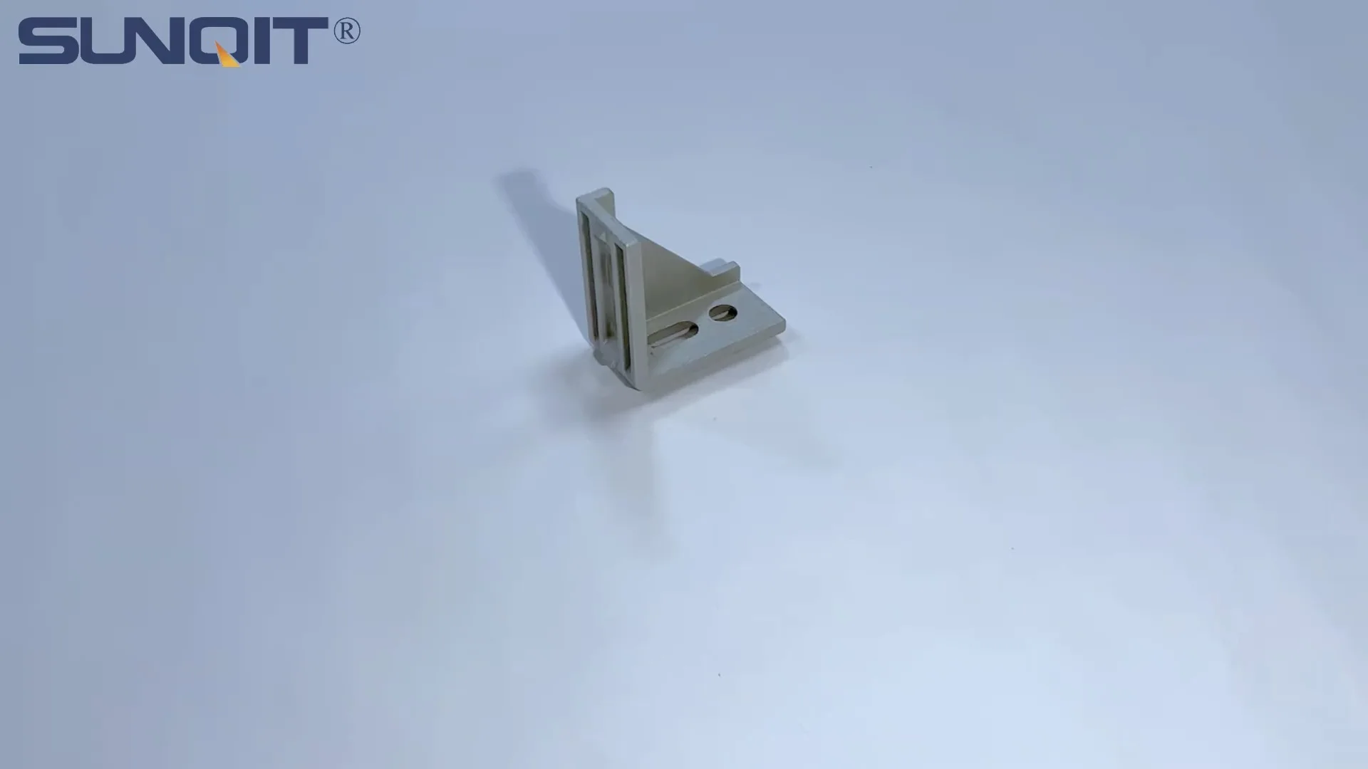
3060 Aluminum Angle Yards
It used for 90° flat connection for 20 series aluminum profile.
In the world of industrial design and manufacturing, the choice of materials can make or break a project. For decades, aluminum extrusion profiles have stood out as a versatile, durable, and cost-effective solution, powering everything from factory workbenches to custom machinery frames. Among these profiles, the 3060 aluminum angle yard has emerged as a unsung hero—offering a unique blend of structural rigidity, adaptability, and ease of integration that makes it a favorite among engineers, hobbyists, and DIY enthusiasts alike. Whether you're designing a lightweight workbench for a home workshop or a heavy-duty material rack for a production floor, mastering the art of CAD design with 3060 aluminum angle yards can transform your ideas from concepts into functional, polished realities. In this guide, we'll dive deep into the nuances of working with this profile, sharing actionable CAD tips, template strategies, and insights into pairing it with the right aluminum profile accessories to elevate your designs.
Understanding 3060 Aluminum Angle Yards: The Basics
Before we jump into CAD tricks and templates, let's start with the fundamentals: What exactly is a 3060 aluminum angle yard, and why should it be on your radar? At its core, it's a type of aluminum extrusion profile—a long, continuous piece of aluminum shaped under high pressure through a die to achieve a specific cross-sectional geometry. The "3060" designation refers to its dimensions: 30mm in one leg, 60mm in the other, with a typical wall thickness ranging from 1.2mm to 2.0mm (depending on the manufacturer and application). The "angle yard" part describes its shape: a right-angle (90-degree) cross-section, similar to an L-bracket but extruded as a single, seamless piece.
What sets this profile apart? For starters, its material composition. Most 3060 aluminum angle yards are made from 6061-T6 aluminum alloy, a heat-treated grade known for its excellent strength-to-weight ratio, corrosion resistance, and machinability. This makes it ideal for both indoor and outdoor use—think factory floors, garage workshops, or even outdoor kiosks. Unlike steel angle irons, which are heavy and prone to rust, aluminum angle yards are lightweight (about 1/3 the weight of steel) and require minimal maintenance, often just a quick wipe-down to keep them looking new.
Another key advantage is modularity. Thanks to the standardized T-slot design found in most aluminum extrusion profiles, 3060 angle yards can be easily connected to other profiles, panels, and accessories using simple fasteners like bolts, nuts, and brackets. This modularity means you can design a structure, assemble it, and then reconfigure it later if your needs change—no welding or specialized tools required. It's a designer's dream for prototyping or projects with evolving requirements.
But perhaps the biggest selling point is its versatility. The 3060 angle yard's unique shape—with two legs of different lengths—makes it perfect for applications where you need both structural support and a mounting surface. For example, the longer 60mm leg can serve as a vertical support, while the shorter 30mm leg can act as a shelf bracket or a mounting point for accessories like lights, tools, or conveyor tracks. This dual functionality reduces the need for extra components, simplifying your design and cutting down on costs.
CAD Design Tips for 3060 Aluminum Angle Yards
Designing with 3060 aluminum angle yards in CAD (Computer-Aided Design) software is where the magic happens. It's where you turn a rough sketch into a precise, buildable plan. But to get the most out of this profile, you'll need to keep a few key principles in mind. Let's break down the essential CAD tips to ensure your designs are accurate, functional, and easy to manufacture.
1. Start with Accurate Measurements (and Tolerances)
The first rule of CAD design with aluminum extrusion profiles? Measure twice, model once. Aluminum extrusions are manufactured to tight tolerances, but even small discrepancies can throw off your assembly—especially when working with accessories like 3060 aluminum profile end caps or connectors. Before you start modeling, obtain the manufacturer's technical datasheet for your 3060 angle yard. This should include critical dimensions like leg length, wall thickness, T-slot width and depth, and corner radius. Input these values into your CAD software exactly as specified—don't round up or down unless the datasheet notes a tolerance range (e.g., ±0.1mm).
Tolerances are particularly important when designing for accessories. For example, if you're adding a 3060 aluminum profile end cap to the end of your angle yard, the cap's inner dimensions must match the profile's outer dimensions closely. A cap that's too loose will fall off; one that's too tight may crack during installation. Most manufacturers provide 3D models or STEP files of their accessories—import these directly into your CAD project to ensure a perfect fit. If STEP files aren't available, use calipers to measure a physical sample of the end cap and model it yourself, adding a 0.05mm–0.1mm clearance to account for manufacturing variations.
2. Leverage Parametric Design for Flexibility
If you're using parametric CAD software (think SolidWorks, Fusion 360, or FreeCAD), take full advantage of its capabilities. Parametric design allows you to define relationships between parts—so if you change the length of a 3060 angle yard, all connected components (like end caps or brackets) automatically adjust to match. This is a game-changer for iterative design, where you might tweak dimensions multiple times.
For example, let's say you're designing a workbench frame using 3060 angle yards for the legs and crossbars. By setting the leg length as a parameter, you can easily adjust the bench height from 800mm to 900mm without having to redraw the entire frame. Similarly, you can create a library of standard 3060 lengths (e.g., 500mm, 1000mm, 1500mm) and swap them in and out as needed. Just be sure to label your parameters clearly—names like "Leg_Length" or "Crossbar_Width" will save you confusion later.
3. Simulate Loads to Avoid Over-Engineering (or Under-Engineering)
One of the biggest mistakes new designers make is either over-engineering (using thicker profiles than necessary, driving up costs) or under-engineering (using profiles that can't support the intended load, leading to failure). To avoid this, use your CAD software's simulation tools to test how your 3060 angle yard structure will perform under real-world conditions.
Start by defining the loads your structure will need to support. For a workbench, this might include the weight of tools (20kg), materials (50kg), and a person leaning on it (70kg), totaling 140kg. Apply these loads to your CAD model and run a stress analysis. Look for areas where the 3060 angle yard bends or deforms excessively—if the deflection exceeds 1mm per meter of length (a common rule of thumb for workbenches), you may need to add additional supports or switch to a thicker-walled profile.
Don't forget to simulate dynamic loads too. If your design includes moving parts—like a rolling cart with 3060 angle yard rails—test how the structure handles vibrations or sudden impacts (e.g., a heavy tool being dropped on the cart). Aluminum is strong, but it's not indestructible; adding gussets or diagonal braces can significantly improve rigidity without adding much weight.
4. Design for Assembly (and Disassembly)
A great CAD design isn't just about how it looks on screen—it's about how easy it is to build in real life. When working with 3060 aluminum angle yards, keep assembly in mind at every step. Ask yourself: Can someone with basic tools (a hex key, wrench, and level) put this together? Will they need a second person to hold parts while tightening fasteners? Can the structure be disassembled for transport or storage?
Here are a few assembly-friendly design tips: - Use accessible fasteners: Avoid placing bolts or nuts in hard-to-reach areas. For example, if you're mounting a shelf to a 3060 angle yard leg, position the T-slot openings so the hex key can reach the bolt head without hitting other parts. - Label parts clearly: In your CAD model, assign part numbers or labels (e.g., "Leg_Front_Left," "Crossbar_Rear") to each 3060 angle yard segment. Include a bill of materials (BOM) that lists quantities, lengths, and accessory types (like end caps or connectors). - Add alignment features: Use tabs, notches, or pilot holes to help align parts during assembly. For example, you could design a bracket with a small notch that fits into the end of a 3060 angle yard, ensuring it sits perfectly square every time. - Consider weight distribution: If your structure is large (like a 2m-tall material rack), break it into smaller subassemblies that can be carried individually and then bolted together. This makes assembly safer and more manageable.
5. Optimize for Material Efficiency
Aluminum extrusion profiles are sold by the meter, so minimizing waste not only reduces costs but also cuts down on environmental impact. Use your CAD software to nest cuts—arrange the lengths of 3060 angle yards you need on a standard 6m or 3m extrusion to maximize yield. For example, if you need four 1.2m legs and two 0.8m crossbars, you could cut a 6m extrusion into five pieces: four 1.2m legs (total 4.8m) and one 1.2m piece, which can be cut down to two 0.8m crossbars (with 0.4m left over for small parts). Most CAD software has nesting tools, or you can use free online tools like CutList Plus to optimize your cuts.
Also, avoid over-specifying lengths. If a crossbar only needs to be 950mm long to span two legs, don't round up to 1000mm "just to be safe"—the extra 50mm adds unnecessary cost and weight. Use your CAD model to measure distances precisely, and add a 5mm–10mm buffer only if the assembly requires adjustability (e.g., for leveling uneven floors).

Creating CAD Templates for 3060 Aluminum Angle Yards
If you find yourself designing multiple projects with 3060 aluminum angle yards, creating reusable CAD templates will save you hours of work. A good template acts as a starting point—pre-loaded with standard parts, dimensions, and design rules that you can tweak for each new project. Let's walk through how to build a template from scratch, using a workbench design as an example.
Step 1: Define the Template Scope
First, decide what your template will include. For a workbench, the core components are: - 3060 aluminum angle yards (legs, front/back rails, side rails) - Aluminum profile accessories (3060 end caps, 90-degree connectors, gussets) - Workbench top (plywood, MDF, or aluminum honeycomb panel) - Optional extras (caster wheels for mobility, tool hooks, shelf brackets)
Keep the template focused on the frame—you can add customizable features (like shelf height or caster type) as variables later. Avoid overcomplicating it with niche components that won't be used in most projects.
Step 2: Set Up Layers and Standards
Organize your CAD file with layers to separate different components. For example: - Layer 1: 3060 Aluminum Angle Yards (legs, rails) - Layer 2: Accessories (end caps, connectors, gussets) - Layer 3: Fasteners (bolts, nuts, washers) - Layer 4: Workbench Top (non-aluminum components) - Layer 5: Annotations (dimensions, labels, BOM)
Set standard units (millimeters are typical for aluminum extrusions) and dimension styles. Use a consistent font and text size for annotations, and define line weights so critical components (like the angle yards) stand out.
Step 3: Model the Base Frame
Start by modeling the basic workbench frame using 3060 angle yards. For a standard workbench, the dimensions might be: - Height: 850mm (comfortable for most users) - Width: 1200mm (adjustable via parameter) - Depth: 600mm (adjustable via parameter)
Model the legs as vertical 3060 angle yards (850mm long), with the 60mm leg facing inward (to provide a mounting surface for the top). The front and back rails will be horizontal 3060 angle yards (1200mm long), connecting the tops of the legs. The side rails (600mm long) will connect the front and back rails, forming a rectangular frame at the top. Add lower rails halfway up the legs for extra stability, and gussets at the corners to prevent racking (side-to-side movement).
Make the width and depth parameters so you can easily resize the bench for different projects. For example, if a client needs a 1500mm-wide bench, simply change the "Width" parameter from 1200mm to 1500mm, and all related components (front/back rails, side rails) will update automatically.
Step 4: Add Standard Accessories
Next, incorporate common aluminum profile accessories into your template. For the workbench, this includes: - 3060 aluminum profile end caps: Add these to the top and bottom of each leg to cover sharp edges and prevent debris from entering the T-slots. Model them as separate parts and position them at the ends of the angle yards. - 90-degree connectors: Use these to join the legs to the rails. Most connectors fit into the T-slots, so model them with the correct dimensions to mate with the 3060 angle yard's T-slot geometry. - Gusset plates: These triangular plates reinforce the corners where legs meet rails. Attach them to both the leg and rail using bolts through the T-slots. - Caster mounts (optional): If the bench needs to be mobile, add caster mounting plates to the bottom of the legs. Ensure the plates are thick enough to support the bench's weight plus load.
Save each accessory as a separate component in your CAD library, so you can drag and drop them into future projects. If you're using Fusion 360, you can even create a "Component Gallery" with all your 3060-related parts for quick access.
Step 5: Test and Refine the Template
Once the template is built, test it by creating a sample workbench design. Check for errors: Are all parts properly constrained? Do the end caps fit without overlapping? Can the fasteners be tightened without interference? If something doesn't work, adjust the template and test again.
Finally, save the template in a shared location (like a cloud drive or company server) with clear versioning (e.g., "Workbench_Template_v2.1"). Include a readme file with instructions on how to use the template, parameter definitions, and links to manufacturer datasheets for the 3060 angle yards and accessories.

Essential Aluminum Profile Accessories for 3060 Angle Yards
A 3060 aluminum angle yard is only as good as the accessories you pair with it. These small but critical components turn a basic extrusion into a functional, polished structure. Below is a breakdown of the most essential accessories, along with their uses, compatibility tips, and installation tricks.
| Accessory Name | Primary Function | Compatibility with 3060 Angle Yards | Installation Tip |
|---|---|---|---|
| 3060 Aluminum Profile End Cap | Covers exposed ends of angle yards to prevent sharp edges, debris buildup, and corrosion. | Designed specifically for 30mm x 60mm angle profiles; check inner dimensions for a snug fit. | Apply a small amount of silicone adhesive to the inside of the end cap before pressing it onto the angle yard for a secure hold (optional for permanent installations). |
| 90-Degree T-Slot Connector | Joins two 3060 angle yards at a right angle (e.g., leg to rail). | Fits T-slots with 8mm–10mm width (common in 3060 profiles); available in plastic, aluminum, or steel. | Tighten the connector bolt gradually to avoid warping the angle yard—alternate between bolts if using a two-bolt connector. |
| Aluminum Gusset Plate | Reinforces corner joints to increase rigidity and prevent racking. | Requires T-slots on both legs of the angle yard; choose a size that covers at least 50mm of each leg. | Install gussets on both the inside and outside of the corner for maximum strength, especially in load-bearing applications. |
| Caster Mounting Bracket | Attaches caster wheels to the bottom of legs for mobility. | Must match the leg dimensions (30mm x 60mm) and have holes aligned with T-slots. | Use locking casters on at least two legs to prevent the structure from rolling unexpectedly. |
| T-Slot Nut and Bolt | Secures accessories (shelves, brackets, tools) to the angle yard's T-slots. | Nut width must match T-slot width (typically M6 or M8 bolts for 3060 profiles). | Slide the nut into the T-slot before attaching the accessory—use a magnetic hex key to hold the bolt in place while tightening. |
3060 Aluminum Profile End Caps: More Than Just a Finishing Touch
Let's take a closer look at one accessory that's often overlooked but incredibly important: the 3060 aluminum profile end cap. At first glance, it might seem like a minor detail—just a plastic or aluminum cap to cover the end of an angle yard. But in reality, end caps serve three critical roles:
1. Safety: Extruded aluminum can have sharp edges at the cut ends, especially if the cut is not perfectly clean. End caps blunt these edges, reducing the risk of cuts during assembly or use. This is especially important for workbenches or material racks that people will interact with daily. 2. Protection: Without end caps, dust, dirt, and liquids can enter the T-slots and internal cavities of the angle yard, leading to corrosion or jamming of fasteners. In outdoor or factory environments, where debris is common, end caps act as a barrier to keep the profile clean. 3. Aesthetics: End caps give your project a polished, professional look. A workbench with exposed angle yard ends looks unfinished; with end caps, it looks intentional and well-designed.
When choosing end caps, opt for color-matched options if possible. Most manufacturers offer end caps in silver (to match aluminum), black, or white. For ESD (Electrostatic Discharge) applications (like electronics manufacturing workbenches), look for conductive end caps that dissipate static electricity.

Real-World Applications: Bringing 3060 Angle Yards to Life
Now that we've covered design tips, templates, and accessories, let's explore how 3060 aluminum angle yards are used in real projects. From workshops to warehouses, these profiles shine in a variety of applications. Here are two common use cases, with insights into how CAD design and accessories come together to create functional solutions.
Case Study 1: DIY Garage Workbench
Mark, a hobbyist woodworker, wanted a sturdy, customizable workbench for his garage. He needed it to support heavy tools (like a table saw and drill press), have storage shelves, and be mobile enough to move out of the way when not in use. After researching materials, he settled on 3060 aluminum angle yards for the frame—drawn to their lightweight design and modularity.
Using Fusion 360, Mark designed a bench with the following specs: - Height: 900mm (taller than standard to reduce back strain) - Width: 1800mm (to fit two tools side by side) - Depth: 750mm (plenty of workspace) - Frame: 3060 angle yards for legs, front/back rails, and shelf supports - Top: 25mm-thick plywood (sanded and sealed) - Accessories: 3060 end caps, 90-degree connectors, locking casters, and shelf brackets
Key CAD decisions: - Mark used parametric design to adjust the bench width—he started with 1500mm but expanded it to 1800mm after realizing he needed more space. - He added gussets at the leg-rail joints to support the table saw's weight (about 80kg). - To save time, he downloaded a 3060 angle yard STEP file from the manufacturer's website and imported it into his project, ensuring accurate dimensions. - He included 3060 end caps in the design to protect his hands from sharp edges when reaching under the bench.
Assembly and outcome: Mark ordered the angle yards cut to length by the supplier (saving him the hassle of cutting them himself) and assembled the frame in an afternoon with a friend. The end caps snapped into place easily, and the locking casters made it simple to roll the bench to the center of the garage when in use. Six months later, he added a second shelf by simply bolting new 3060 angle yards to the existing frame—no redesign needed.
Case Study 2: Factory Material Rack
A small electronics manufacturer needed a material rack to store circuit boards and components on the production floor. The rack had to be ESD-safe (to prevent static damage to components), adjustable (to accommodate different board sizes), and durable enough to withstand daily use by factory workers.
The engineering team chose 3060 aluminum angle yards for the uprights and crossbars, paired with ESD-safe accessories like black ESD end caps and conductive T-slot nuts. Using SolidWorks, they designed a rack with: - Height: 1800mm (with 5 adjustable shelves) - Width: 1200mm - Depth: 450mm - Uprights: 3060 angle yards (60mm leg facing outward to mount shelves) - Shelves: ESD-safe plywood supported by 3060 angle yard brackets - Accessories: 3060 ESD end caps, adjustable shelf pins, and ESD grounding straps
Key CAD decisions: - The team simulated the rack's load capacity, ensuring each shelf could hold 50kg of components without sagging. - They added slots in the uprights every 50mm to allow shelf height adjustments, using parametric design to space the slots evenly. - ESD end caps were modeled with conductive inserts to ensure the entire rack was grounded—critical for protecting sensitive electronics.
Assembly and outcome: The rack was assembled on-site by the maintenance team, who followed the CAD-generated instructions and BOM. The adjustable shelves proved invaluable as the factory added new product lines, and the ESD end caps prevented static buildup. Two years later, the rack is still in use, with only minor wear on the caster wheels (easily replaced with new ones from the manufacturer).
Troubleshooting Common CAD Design Issues with 3060 Angle Yards
Even with careful planning, CAD designs with 3060 aluminum angle yards can hit snags. Here are some common issues and how to fix them:
Issue 1: Parts Don't Align During Assembly
Cause: Incorrect T-slot spacing or tolerance mismatches between angle yards and accessories. Solution: Double-check the T-slot dimensions in your CAD model against the manufacturer's datasheet. If using third-party accessories, import their STEP files to ensure compatibility. Add 0.1mm–0.2mm clearance between mating parts to account for manufacturing variations.
Issue 2: Structure Is Wobbly or Unstable
Cause: Insufficient bracing, undersized angle yards, or loose fasteners. Solution: Run a structural simulation in CAD to identify weak points. Add diagonal braces or gussets to improve rigidity. If the angle yard is bending, switch to a thicker-walled version (e.g., 2.0mm instead of 1.2mm). Tighten all fasteners to the manufacturer's recommended torque (typically 4–6 Nm for M6 bolts).
Issue 3: Accessories Crack or Break During Installation
Cause: Over-tightening fasteners, using plastic accessories for heavy loads, or incompatible accessory dimensions. Solution: Use a torque wrench to avoid over-tightening. For load-bearing applications, choose metal (aluminum or steel) accessories instead of plastic. Ensure the accessory's load rating matches or exceeds the expected weight.
Conclusion: Design Smarter with 3060 Aluminum Angle Yards
Designing with 3060 aluminum angle yards is a blend of art and science. It requires an understanding of the profile's strengths, a mastery of CAD tools, and a keen eye for how accessories can elevate functionality. Whether you're building a workbench for your garage, a material rack for a factory, or a custom machine frame, the 3060 angle yard offers the versatility, strength, and modularity to bring your ideas to life.
By following the CAD tips outlined here—starting with accurate measurements, leveraging parametric design, and prioritizing assembly—you can create designs that are not only functional but also easy to build and adapt. Pairing your angle yards with the right accessories, like 3060 aluminum profile end caps and connectors, ensures a polished, professional finish. And with reusable templates, you'll save time on future projects, letting you focus on what matters most: innovating.
So, the next time you're staring at a blank CAD screen, remember: The 3060 aluminum angle yard isn't just a piece of metal—it's a canvas for creativity. With the right approach, it can transform your design from a concept into something tangible, durable, and uniquely yours.