
In the world of lean manufacturing, every component counts. From the largest workbench to the smallest connector, precision and compatibility can make or break the efficiency of a production line. One such unsung hero? The turning angle code 4040 . This unassuming piece of hardware is the glue that holds aluminum profiles together, ensuring stability in everything from material racks to assembly stations. But here's the thing: if your 3D model of this angle code is off by even a millimeter, you could be looking at wobbly workbenches, misaligned conveyor tracks, or worse—delays in production. So today, let's roll up our sleeves and walk through how to 3D model a turning angle code 4040 like a pro, ensuring your CAD-designed lean system runs as smoothly as a well-oiled machine.
First Things First: What Even Is a Turning Angle Code 4040?
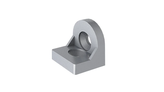
Before we dive into modeling, let's make sure we're all on the same page. If you've ever stood in a factory or warehouse and admired how neatly the aluminum frames of workbenches or flow racks are put together, chances are you've seen a turning angle code 4040 in action. It's a small, usually L-shaped bracket made from aluminum (though sometimes steel) designed to connect two 4040 aluminum profiles at a right angle. Think of it as the cornerstone of your lean system's structure—without it, those profiles would just be loose pieces of metal, not a sturdy workstation or material handling rack.
Why 4040? That refers to the profile's dimensions: 40mm by 40mm, a standard size in lean manufacturing for its balance of strength and versatility. The "turning" part? It lets you pivot the connection slightly if needed, though most often it's fixed at 90 degrees. And "code"? Just industry jargon for a standardized part number, making it easy to order replacements or integrate into designs.
But here's why it matters for your CAD-designed lean system: this tiny bracket bears the weight of whatever's on the profile—tools, parts, even workers leaning on a workbench. A poorly modeled angle code might have holes that don't line up with the profile's T-slots, or a thickness that's too thin to handle the load. That's where 3D modeling comes in. By creating a digital twin of the angle code, you can test its fit, stress, and compatibility before a single piece of metal is cut.
Why 3D Modeling Beats 2D Drawings for Lean System Components
You might be thinking, "Can't I just sketch this in 2D and call it a day?" Sure, but let's say you do. You draw the top view, note the hole positions, and send it off to the shop. A week later, the brackets arrive—and when you try to bolt them to your 4040 aluminum profiles, the holes are 2mm too far left. Suddenly, your entire assembly line is on hold while you reorder parts. Not exactly "lean," is it?
3D modeling eliminates that guesswork. Here's how:
- Spatial Awareness: 2D drawings can hide depth and angle nuances. A 3D model lets you rotate the angle code, zoom in on the thickness of the flanges, and check how it sits against the profile's grooves—no more "oops, that hole is on the wrong side" moments.
- Fit Testing: Most CAD software lets you import models of standard aluminum profiles (or draw your own). You can virtually bolt the angle code to the profile and run interference checks to ensure nothing clashes—like a bolt head sticking out where a roller track needs to go.
- Stress Simulation: Tools like SolidWorks or Fusion 360 let you apply forces to the model (e.g., the weight of a 50kg toolbox on the workbench) and see where the angle code might bend or crack. This is gold for avoiding costly failures down the line.
- Integration with the Big Picture: Your lean system isn't just angle codes and profiles—it's roller tracks , casters, workbenches, and more. A 3D model of the angle code can be dropped into a larger assembly, ensuring it plays nice with every other component.
Think of it like building a puzzle. If each piece (angle code, profile, roller track) is a 3D model, you can test how they fit together before gluing anything down. That's the power of 3D in lean design.

Step-by-Step: Modeling Turning Angle Code 4040 in CAD
Ready to get your hands dirty? Let's walk through the process, using Fusion 360 as an example (it's free for hobbyists and startups, and great for beginners). We'll break it down into 8 actionable steps.
Step 1: Gather Your Measurements (No Guessing Allowed)
First, you need to know exactly what you're modeling. If you're reverse-engineering an existing angle code, grab a caliper and measure everything: length of the flanges (how far they stick out from the corner), width of each flange, thickness (critical for strength), hole diameter (for bolts), and hole positions (distance from the edges and between holes).
Pro tip: If you're designing a custom angle code (not replicating a standard one), start with the 4040 aluminum profile's specs. The T-slots on a 4040 profile are usually 8mm wide, with centers 32mm apart (standard for EU profiles). Your angle code's holes should align with these slots so bolts can pass through easily. For example, if the profile has a slot every 32mm, placing a hole 16mm from the end of the angle code's flange ensures it lines up with the first slot.
Write all these numbers down in a spreadsheet—you'll refer to them constantly. Example measurements might look like this:
| Dimension | Measurement | Why It Matters |
|---|---|---|
| Flange Length (Each Side) | 50mm | Determines how much surface area connects to the profile |
| Flange Width | 30mm | Must fit within the profile's 40mm width without overhang |
| Thickness | 4mm | Thinner = lighter but weaker; thicker = stronger but heavier |
| Hole Diameter | 8.5mm | Slightly larger than an M8 bolt (8mm) for easy insertion |
| Hole Position from Flange End | 16mm | Aligns with 4040 profile's T-slot spacing |
Step 2: Fire Up Your CAD Software (We're Using Fusion 360 Here)
Open Fusion 360 and start a new design. Click "New Component" to keep your angle code separate from other parts (good practice for assemblies later). Name it "Turning Angle Code 4040" so you can find it easily.
Step 3: Sketch the Base Profile (Start with 2D, Then Go 3D)
Click "Sketch" and select the "Front Plane." This is where you'll draw the outline of the angle code's front view. Using the line tool, draw an L-shape with the flange lengths you measured (e.g., 50mm on each side). Then, use the "Offset" tool to thicken the lines by your flange width (30mm)—this creates the flat, rectangular flanges of the bracket.
Next, add the holes. Use the "Circle" tool to draw holes at the positions you noted (e.g., 16mm from each end of the flanges). Make sure the circles are centered on the flange's width—you don't want a hole too close to the edge, which could weaken the flange.
Pro tip: Use the "Dimension" tool to lock in all measurements. Click a line, drag out the dimension, and type in your number (e.g., 50mm for flange length). This makes the sketch parametric—if you later need to adjust the flange length to 55mm, you can just change the dimension, and the whole sketch updates.
Step 4: Extrude to 3D (Add Thickness)
Now it's time to turn your flat sketch into a 3D object. Click "Extrude," select the area of the sketch you want to extrude (the entire L-shape, minus the holes), and type in your thickness measurement (e.g., 4mm). Hit "OK," and suddenly—you've got a 3D angle code! The holes are still just circles in the sketch, though, so we need to cut those out.
Click "Extrude" again, but this time select the hole circles and choose "Cut" instead of "Join." Extrude the cuts all the way through the bracket (type "4mm" as the distance, since that's the thickness). Now you've got a solid 3D model with holes—looking good!
Step 5: Refine the Details (Fillets and Chamfers = Safety + Style)
Sharp edges on metal brackets are a safety hazard (ever cut your hand on a raw steel corner?) and can weaken the part. Use the "Fillet" tool to round off the outer corners of the angle code. A 2mm fillet is usually enough to make it safe without compromising strength.
You might also want to chamfer the inner corner (where the two flanges meet) to make welding or painting easier later, but that's optional. For most lean system applications, filleted outer edges are the priority.
Step 6: Assign Material Properties (For Real-World Simulation)
Now that the shape is done, tell the CAD software what the angle code is made of. In Fusion 360, right-click the component in the browser, select "Physical Material," and choose "Aluminum Alloy" (e.g., 6061, a common choice for structural parts). This lets the software calculate weight, thermal properties, and even stress limits—critical for the next step.
Step 7: Test It (Stress Analysis and Fit Checks)
Let's make sure this bracket can actually do its job. First, check the fit with a 4040 aluminum profile. If you don't have a 3D model of the profile, draw a quick one: a 40mm x 40mm square extrusion with T-slots (you can find standard 4040 profiles online and import them as STEP files). Assemble the angle code and profile by aligning the holes, then add a virtual bolt (use the "Cylinder" tool to draw an M8 bolt, then "Mate" it to the hole). Rotate the assembly—does everything line up? Are the bolt heads sitting flush, or sticking out where they'll interfere with a roller track later?
Next, run a stress test. In Fusion 360, go to the "Simulation" workspace, set up a study, and apply a force to the end of one flange (simulating the weight of a load on the profile). For example, apply 500N (about 50kg) downward. The software will color-code the model to show where stress is highest—red means danger, green means good. If the corners are turning red, you might need to thicken the flanges or add a reinforcing rib (a small, triangular piece between the flanges).
Step 8: Export the Model (Ready for Manufacturing)
Once you're happy with the model, export it in a format your manufacturer can use. For CNC machining, STEP or IGES files are standard—they're universal and work with most CAM software. For 3D printing, STL is better. If you need 2D drawings for documentation (e.g., to show hole positions to the shop), use the "Drawing" workspace to generate orthographic views with dimensions.
And that's it! You've gone from measurements to a validated 3D model of the turning angle code 4040. Pat yourself on the back—you're one step closer to a rock-solid lean system.

CAD Software Showdown: Which Tool Should You Use?
Not all CAD software is created equal, especially when it comes to modeling small, precise components like angle codes. Here's a quick breakdown of the top options, based on ease of use, features, and cost:
| Software | Ease of Use (1-5) | Precision Tools | Aluminum Profile Libraries | Cost |
|---|---|---|---|---|
| Fusion 360 | 4/5 | Parametric modeling, stress simulation, 3D printing tools | Yes (user-uploaded libraries for aluminum profiles) | Free for startups/hobbyists; $60/month pro |
| SolidWorks | 3/5 (steeper learning curve) | Advanced assembly design, finite element analysis (FEA) | Yes (built-in libraries for standard profiles) | $3,995 one-time (standard license) |
| AutoCAD | 3/5 (great for 2D, less intuitive for 3D) | Basic 3D modeling, precise drafting tools | Limited (better for custom profile drawing) | $220/month |
| FreeCAD | 2/5 (open-source, less polished UI) | Parametric modeling, customizable workbenches | Yes (community-created aluminum profile libraries) | Free |
For most lean system designers, Fusion 360 hits the sweet spot: it's affordable, has all the tools you need for 3D modeling and simulation, and integrates well with other manufacturing workflows. If you're working in a large enterprise with complex assemblies, SolidWorks might be worth the investment for its advanced FEA tools. But for startups or small shops? Fusion 360 is hard to beat.
Common Pitfalls to Avoid (Because Mistakes Cost Money)
Even with careful modeling, it's easy to trip up. Here are the top mistakes to watch for:
- Ignoring Standard Sizes: If you're designing for a 4040 aluminum profile, don't invent your own T-slot spacing. Stick to industry standards (32mm for EU profiles, 20mm for some Asian profiles) so your angle code works with off-the-shelf bolts and accessories.
- Underestimating Loads: That 4mm thickness might seem fine, but if your workbench will hold heavy machinery, it could bend. Always run stress tests with realistic loads—better to over-engineer a little than have a bracket fail.
- Forgetting Tolerances: Manufacturing isn't perfect. A CNC machine might drill a hole 0.1mm larger than your model, or a saw might cut a flange 0.5mm shorter. In your CAD model, add tolerances (e.g., "Hole diameter: 8.5mm ±0.1mm") to give the shop wiggle room.
- Overcomplicating the Design: Unless you need a custom angle code for a unique application, stick to simple shapes. Fancy curves or cutouts might look cool, but they add cost to machining and can weaken the part.
Remember: lean manufacturing is about efficiency. Your 3D model should reflect that—simple, precise, and built to work with the rest of your system.
From Angle Code to Lean System: The Big Picture
So you've modeled the turning angle code 4040—now what? This tiny bracket is just one piece of a much larger puzzle: your entire lean system. Let's zoom out and see how it fits in.
Imagine you're building a material rack for a factory floor—let's call it "Material Rack B (3 Row and 3 Floor)" from your keyword list. This rack uses 4040 aluminum profiles for the frame, connected by turning angle codes 4040 at each corner. Between the profiles, you'll add roller tracks to let bins slide smoothly from one level to the next. The angle codes ensure the frame is square and sturdy, so the roller tracks stay aligned, and the bins don't jam.
Now, if your angle code model is off, the frame might wobble, the roller tracks might slope unevenly, and suddenly, workers are struggling to slide bins—wasting time and energy. But with a precise 3D model, you can assemble the entire rack virtually first: angle codes, profiles, roller tracks, even the casters at the bottom. You can check if the rack fits through doorways, if the roller tracks are at the right height for ergonomics, and if the whole thing can support the weight of loaded bins.
That's the power of 3D modeling for lean systems: it lets you optimize the entire workflow, not just individual parts. And when every component—from the turning angle code 4040 to the aluminum guide rails—works in harmony, you get the efficiency, safety, and scalability that lean manufacturing is all about.
Final Thoughts: Small Part, Big Impact
At the end of the day, the turning angle code 4040 might not be the most glamorous component in your lean system. It won't get featured in company brochures or win design awards. But without it, your aluminum profiles are just sticks, your workbenches are unstable, and your roller tracks are misaligned. It's the quiet foundation that holds everything together.
And in lean manufacturing, foundations matter. Taking the time to 3D model this small bracket—measuring twice, simulating the stress, testing the fit—isn't just about precision. It's about respecting the process, valuing efficiency, and ensuring that every part of your system works as hard as your team does.
So the next time you fire up your CAD software, remember: you're not just drawing a bracket. You're building a lean system that will streamline production, reduce waste, and keep your team moving forward. And that? That's worth every millimeter of precision.