- Company Articles
- Products and Technology
- Product knowledge
- How to Calculate Load Capacity for Aluminum Guide Rail A in Your System

How to Calculate Load Capacity for Aluminum Guide Rail A in Your System
Related Product
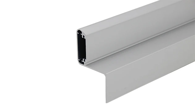
Aluminum Guide Rail A
The aluminum guide rails hold the transport goods securely on the roller track. For installation, the guide rails are simply pushed over the roller tracks.To protect sensitive products.
Why Load Capacity Matters for Your Aluminum Guide Rail A
Let's start with a scenario we've all seen in manufacturing: A production line humming along, parts gliding smoothly along a flow rack—until suddenly, a guide rail bends under the weight, jamming the entire process. Downtime, frustrated teams, delayed orders… none of us need that. That's exactly why understanding how to calculate the load capacity of your Aluminum Guide Rail A isn't just a "nice-to-know"—it's the backbone of a reliable, efficient lean system.
Aluminum Guide Rail A is more than just a metal bar in your setup. It's the silent workhorse in everything from conveyor systems moving delicate 3C components to workbenches assembling medical devices. Its ability to handle weight safely directly impacts your line's speed, worker safety, and even the lifespan of your entire lean pipe system. And since we're talking about lean principles here—maximizing value, minimizing waste—getting this right means you won't overspend on overbuilt rails or risk disaster with underrated ones.
In this guide, we'll walk through the step-by-step process of calculating load capacity for Aluminum Guide Rail A. We'll keep it practical, with real-world examples (think: a 3-row material rack in a warehouse or a single-deck workbench in a 3C assembly line) and even a handy reference table. By the end, you'll not only have the numbers but also the confidence to optimize your system for both safety and efficiency.
Step 1: Know Your Aluminum Guide Rail A's Basics
Before crunching numbers, let's get familiar with the star of the show: Aluminum Guide Rail A. What makes it different from other rails, and why does that matter for load capacity?
Material Matters: The Aluminum Advantage
Aluminum Guide Rail A is made from high-grade aluminum extrusion profile—lightweight, corrosion-resistant, and surprisingly strong. Unlike heavier steel rails, its strength-to-weight ratio is a game-changer for lean systems, where flexibility and portability are key. But "aluminum" isn't a one-size-fits-all term. The specific alloy (we use 6063-T5, a common choice for industrial profiles) and wall thickness directly affect how much weight it can handle.
For example, our standard Aluminum Guide Rail A has a wall thickness of 1.2mm, but we also offer 1.5mm and 2.0mm options for heavier loads. Think of it like choosing a water pipe: a thinner pipe might work for a garden hose, but you'd need a sturdier one for a fire hydrant. The same logic applies here.
Profile Design: T-Slots and Cross-Section
Take a close look at Aluminum Guide Rail A, and you'll notice its T-slot design. Those slots aren't just for looks—they're engineered to distribute weight evenly along the rail's length. The cross-section (the shape when you cut the rail perpendicular to its length) is critical here. A rectangular profile with reinforced edges (like ours) will resist bending better than a flat, thin strip of aluminum.
To visualize this: imagine holding a ruler flat and pressing down on the middle—it bends easily. Now rotate the ruler so its edge faces up, and try pressing again. It's much stiffer. That's the power of cross-sectional design, and it's why we can't ignore it when calculating load capacity.
Quick Tip:
If you're unsure about your rail's specs (alloy, wall thickness, cross-section), check the product label or reach out to your supplier. At SunQit, every Aluminum Guide Rail A comes with a detailed spec sheet—no guesswork needed!

Step 2: Key Factors That Affect Load Capacity
Load capacity isn't just about the rail itself—it's a dance between the rail, how you install it, and what you're asking it to do. Let's break down the four main factors:
1. Span Length: How Far Apart Are Your Supports?
The "span" is the distance between two supports (like the legs of a workbench or the brackets holding up a flow rack). This is the single biggest factor in load capacity. A rail supported every 50cm can carry far more weight than one stretched over 2 meters. Why? Because the longer the span, the more the rail will bend under load—think of a diving board: the farther you walk out, the wobblier it gets.
2. Load Type: Static vs. Dynamic Weight
Are you placing a stationary box on the rail (static load) or sliding parts along it all day (dynamic load)? Dynamic loads are trickier—they add extra stress from movement, vibration, or sudden stops. For example, a conveyor moving circuit boards at 0.5m/s will exert more force on the rail than the same boards sitting still on a material rack.
3. Installation: How Securely Is It Mounted?
Even the strongest rail will fail if it's mounted poorly. Using flimsy brackets or loose screws? That's like building a house on sand. We recommend using our aluminum profile accessories—like the roller track placon mount for aluminum profile flat or high—designed to lock the rail firmly to your lean pipe structure. The more secure the connection, the more weight the rail can transfer safely to the supports.
4. Environment: Temperature, Moisture, and Usage
Extreme heat (like near ovens in automotive plants) can slightly weaken aluminum, while constant moisture (common in food processing) might lead to corrosion over time—weakening the rail's structure. And let's not forget usage frequency: a rail in a high-throughput 3C assembly line (running 24/7) will wear faster than one in a low-volume medical device workshop. Always factor in your daily operating conditions!

Step 3: The Calculation Formula (It's Simpler Than You Think)
Okay, let's get to the math. Don't worry—we'll avoid complex engineering jargon. The basic formula for maximum load capacity (for a rail supported at both ends, the most common setup) is:
Maximum Load (kg) = (Material Strength × Section Modulus) / Span Length
Breaking Down the Formula
- Material Strength: For Aluminum Guide Rail A (6063-T5 alloy), this is typically 110 MPa (megapascals), a measure of how much stress the material can take before bending.
- Section Modulus (Z): This is a number that describes the rail's cross-sectional shape and its ability to resist bending. For our standard Aluminum Guide Rail A (30mm × 30mm with 1.2mm wall), Z is approximately 1.8 cm³ (cubic centimeters). (Check your spec sheet for exact values—thicker walls mean higher Z!)
- Span Length: The distance between supports, measured in meters (m).
Example 1: A Basic Workbench Setup
Let's say you're using Aluminum Guide Rail A on a single-deck Workbench E (without casters) in a 3C assembly line. The rail spans 1 meter (between the workbench legs). Using the formula:
Let's say you're using Aluminum Guide Rail A on a single-deck Workbench E (without casters) in a 3C assembly line. The rail spans 1 meter (between the workbench legs). Using the formula:
Maximum Load = (110 MPa × 1.8 cm³) / 1 m
First, convert units to keep things consistent: 1 MPa = 10 kg/cm², so 110 MPa = 1100 kg/cm².
Now calculate: (1100 kg/cm² × 1.8 cm³) / 100 cm (since 1m = 100cm) = 19.8 kg.
Wait—that seems low? Not exactly. Remember, this is the maximum load at the center of the span (the weakest point). In reality, workbench loads are often distributed (tools, parts spread out), so the rail can handle more. For distributed loads, multiply the result by 1.5: 19.8 kg × 1.5 = ~30 kg. That's a realistic capacity for a workbench rail holding small assembly tools and components!
Example 2: A Flow Rack in Warehouse Logistics
Now, let's scale up: a Material Rack B (3 rows, 3 floors) using Aluminum Guide Rail A to slide boxes of inventory. The rail spans 1.5 meters (between vertical supports). We're using the 1.5mm wall version here, so Z increases to 2.5 cm³.
Now, let's scale up: a Material Rack B (3 rows, 3 floors) using Aluminum Guide Rail A to slide boxes of inventory. The rail spans 1.5 meters (between vertical supports). We're using the 1.5mm wall version here, so Z increases to 2.5 cm³.
Maximum Load = (110 MPa × 2.5 cm³) / 1.5 m
Convert: 110 MPa = 1100 kg/cm²; 1.5m = 150cm.
Calculation: (1100 × 2.5) / 150 = 2750 / 150 ≈ 18.3 kg (center load). For distributed boxes (each row holding 5 boxes, ~2kg each = 10kg total), that's well within capacity. And if you add a center support (using our roller track placon mount center support bracket), the span drops to 0.75m, boosting capacity to ~36 kg—plenty for heavier items!
Quick Reference: Load Capacity Table for Aluminum Guide Rail A
To save you time, here's a table showing approximate maximum distributed load capacities for common spans and wall thicknesses. Remember, these are guidelines—always verify with your specific setup!
| Aluminum Guide Rail A Wall Thickness | Span Length (m) | Maximum Distributed Load (kg) | Common Application |
|---|---|---|---|
| 1.2mm | 0.5 | 60-70 kg | Small conveyor sections, workbench edges |
| 1.2mm | 1.0 | 25-30 kg | Single-deck workbenches (Workbench E) |
| 1.5mm | 1.0 | 40-45 kg | Medium-duty flow racks (Material Rack B, 2-row) |
| 1.5mm | 1.5 | 20-25 kg | Longer conveyor runs, 3-row material racks |
| 2.0mm | 1.5 | 35-40 kg | Heavy-duty applications (automotive parts, large medical devices) |
Pro Tip:
When in doubt, add supports! Even a simple center bracket (like our roller track placon mount center support bracket) can cut span length in half and nearly double load capacity. It's a cheap, easy way to boost safety without upgrading to a thicker rail.
Step 4: Real-World Adjustments (Because Manufacturing Isn't Perfect)
Calculations give you a baseline, but real factories aren't labs. Here are the "real-world" adjustments you need to make to ensure your numbers hold up:
Factor in Dynamic Loads
Earlier, we mentioned dynamic loads (moving weight). For conveyors or flow racks where items slide or roll, multiply your calculated static load by 0.7 (a 30% safety factor). Why? Sudden starts/stops or uneven sliding can create "shock loads" that stress the rail more than static weight. For example, a 30 kg static load becomes 21 kg when moving—still safe, but important to account for.
Check for Combined Stresses
Is your Aluminum Guide Rail A only holding vertical weight, or is there also side-to-side force? For example, in a conveyor with plastic roller track guide rails (yellow or grey), items might push against the rail as they turn. This lateral stress reduces the rail's vertical load capacity. If lateral forces are significant, reduce your calculated load by another 10-15%.
Don't Forget Wear and Tear
Aluminum is durable, but over time, scratches, corrosion, or loose connections can weaken the rail. If your system is older than 2-3 years, or in a high-wear environment (like a busy warehouse), assume a 5-10% reduction in load capacity. Regular inspections (tightening brackets, cleaning corrosion) can help maintain performance!
When to Customize: Beyond the Basics
What if your load requirements fall outside the table above? Maybe you need a 2-meter span for a custom conveyor, or you're moving extremely heavy parts (think: automotive components). This is where lean principles and customization go hand-in-hand. Instead of overbuying a thick, heavy rail, we can design a solution that balances strength and efficiency—like adding intermediate supports, using a higher-wall rail, or combining Aluminum Guide Rail A with parallel aluminum pipe for extra rigidity.
For example, a client in the medical device industry needed a flow rack that could handle 50 kg loads over a 1.8m span. Instead of jumping to a 2.0mm rail (which would work but add unnecessary weight), we added two lightweight aluminum guide rail B supports in the middle, cutting the effective span to 0.6m. The result? A rail that handled the load, weighed 30% less than a thicker option, and cost less—true lean optimization!
And since all our components are designed for reusability, you can even repurpose rails from old systems. Need to upgrade a workbench to handle heavier tools? Swap out a 1.2mm rail for a 1.5mm one, reuse the same brackets, and you're good to go—no waste, no extra cost for parts.
Final Thoughts: Load Capacity as Part of Your Lean Journey
Calculating load capacity for Aluminum Guide Rail A isn't just about numbers—it's about building a system that works for your team, not against them. When your rails handle weight safely, you eliminate downtime, reduce worker frustration, and keep your lean pipe system running at peak efficiency. And isn't that the goal? To create a workspace where every component—from the basic aluminum tube to the internal rotary aluminum joint—pulls its weight (pun intended) to deliver value.
Whether you're setting up a new lean system, upgrading an existing one, or just troubleshooting a wobbly rail, remember: the formula is simple, but the context matters. Span length, installation, load type—all these pieces come together. And if you ever feel stuck, we're here to help. Our team of engineers specializes in turning load requirements into practical, cost-effective designs—because your success is our success.
So go ahead: measure that span, check that wall thickness, and calculate with confidence. Your lean system (and your bottom line) will thank you.