- Company Articles
- Products and Technology
- Product knowledge
- How to Calculate Load Capacity for Structures Using Two Way Aluminum Pipe Joints

How to Calculate Load Capacity for Structures Using Two Way Aluminum Pipe Joints
Related Product
Two Way Aluminum Pipe Joint
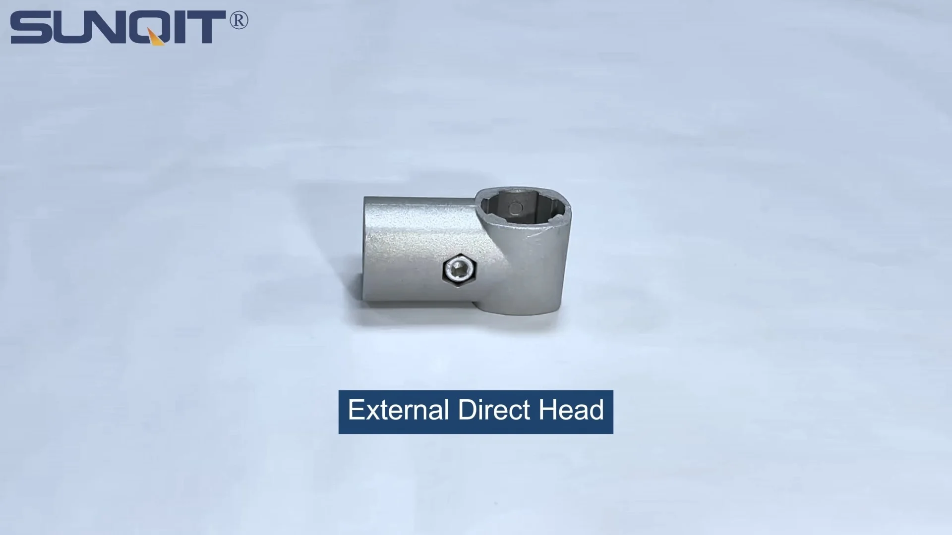
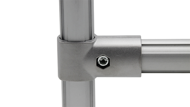
Aluminum 2 way pipe joint for 28mm aluminum pipe connection in 2 direction.
In the world of industrial manufacturing, warehouse operations, and lean system setups, the difference between a smooth workflow and a costly disaster often comes down to one critical factor: load capacity. Whether you're building a workbench for assembly lines, a material rack for inventory storage, or a custom conveyor system, understanding how much weight your structure can safely hold isn't just a best practice—it's essential for protecting your team, your equipment, and your bottom line. At the heart of many of these structures lies a humble yet powerful component: the two way aluminum pipe joint. These unassuming connectors are the glue that holds aluminum profiles, pipes, and accessories together, and their performance directly impacts how much weight your structure can bear. In this guide, we'll walk through the step-by-step process of calculating load capacity for structures using two way aluminum pipe joints, breaking down complex engineering principles into practical, actionable advice.
Understanding the Basics: What Are Two Way Aluminum Pipe Joints?
Before diving into calculations, let's start with the fundamentals. Two way aluminum pipe joints are specialized connectors designed to join two aluminum pipes or profiles at a fixed angle (typically 90 degrees, though some are adjustable). Unlike rigid welding or permanent fasteners, these joints offer flexibility—allowing for quick assembly, disassembly, and reconfiguration, which is why they're a staple in lean manufacturing and modular setups. Made from high-strength aluminum alloys (often 6061 or 6063, known for their excellent balance of strength and lightweight properties), these joints feature internal threads, clamping mechanisms, or friction-fit designs that secure pipes in place while distributing weight evenly across the structure.
But why aluminum? Aluminum profiles and pipes are favored in industrial settings for several reasons: they're lightweight, resistant to corrosion, and offer impressive strength-to-weight ratios. When paired with two way joints, they create structures that are both sturdy and adaptable—perfect for dynamic environments where workflows or storage needs change over time. Common applications include workbenches, turnover trolleys, material racks, and even custom machinery guards. In each case, the two way joint acts as a pivot point for load distribution, making its load capacity a key variable in the overall structural integrity.
Key Factors Influencing Load Capacity
Calculating load capacity isn't as simple as looking up a single number on a product spec sheet. Instead, it requires considering a combination of factors that interact to determine how much weight a structure can safely support. Let's break down the most critical variables:
1. Material Properties: Aluminum Pipes and Joint Strength
The first piece of the puzzle is the material itself. Aluminum pipes (or profiles) and two way joints have inherent strength limits based on their composition, thickness, and manufacturing process. For aluminum pipes, the key metric is yield strength —the maximum stress a material can withstand before it begins to deform permanently. Most industrial-grade aluminum pipes used in structural applications have a yield strength between 10,000 and 40,000 psi (pounds per square inch), depending on the alloy and wall thickness. Thicker pipes (e.g., 2.0mm wall vs. 1.0mm wall) will naturally handle more weight, as they have a larger cross-sectional area to resist bending and compression.
Two way joints, on the other hand, are tested for shear strength and tensile strength . Shear strength refers to the joint's ability to resist forces that try to slide its components past each other (e.g., when a heavy load pushes down on a workbench, the joints holding the legs to the tabletop experience shear stress). Tensile strength, meanwhile, is the resistance to forces that try to pull the joint apart (e.g., when a material rack is overloaded, the joints may experience tension as the pipes bend outward). Most reputable manufacturers provide shear and tensile strength ratings for their two way joints—for example, a standard two way aluminum joint might have a shear strength of 500 lbs and a tensile strength of 800 lbs. These numbers are critical benchmarks for your calculations.
2. Joint Configuration and Angle
Not all two way joint installations are created equal. The angle at which pipes meet, the tightness of the joint, and the direction of the load all affect how much weight the joint can handle. For example, a two way joint connecting two pipes at a 90-degree angle (like the corner of a workbench) will distribute load differently than one connecting pipes at a 45-degree angle (common in diagonal bracing). In general, joints aligned with the direction of the load (i.e., compression forces) are stronger than those subjected to lateral or torsional (twisting) forces. Additionally, the way the joint is fastened—whether via set screws, bolts, or friction clamps—impacts its grip on the pipes. A loose joint, even if rated for high shear strength, will fail prematurely under load because it allows for movement, which creates stress concentrations.
3. Structural Geometry: Span Length and Support Spacing
Imagine building a simple workbench with four legs and a top made from aluminum profiles connected by two way joints. If the top spans 6 feet between the legs, it will bend more under load than if the span were only 3 feet. This is because the longer the span (the distance between supports), the greater the bending stress on the pipes and joints. Engineers refer to this as the moment of inertia —a measure of how resistant a pipe is to bending, which depends on its cross-sectional shape and size. For example, a square aluminum profile will have a higher moment of inertia than a round pipe of the same material and weight, making it stiffer and better suited for long spans.
Support spacing is equally important. Adding intermediate supports (like a center brace under a workbench top) reduces the effective span, lowering bending stress and increasing load capacity. In fact, doubling the number of supports can often more than double the structure's weight-bearing ability. When designing your structure, ask: Where are the critical spans? Can you add supports to shorten them? The answers will directly influence your load capacity calculations.
4. Environmental and Load Type Factors
Load capacity isn't static—it changes based on how the load is applied and the conditions in which the structure operates. Static loads (e.g., a stack of boxes sitting on a material rack) are easier to calculate because they apply constant, predictable force. Dynamic loads (e.g., a heavy component being slid onto a workbench or a trolley rolling over a conveyor) are more complex, as they introduce (impact forces) that can exceed the static load by 2–3 times. For example, dropping a 50-pound part onto a workbench isn't the same as placing it gently— the impact could momentarily double or triple the force on the joints and pipes.
Environmental factors also play a role. High temperatures can weaken aluminum (though aluminum retains most of its strength up to 200°F), while humidity or corrosive environments may degrade joint components over time. If your structure is outdoors or in a factory with chemical exposure, you may need to factor in a lower load capacity to account for material degradation.
Step-by-Step Guide to Calculating Load Capacity
Now that we've covered the key factors, let's put this knowledge into practice. Calculating load capacity for a structure using two way aluminum pipe joints involves four main steps: gathering material specs, analyzing the structure's geometry, calculating stress on pipes and joints, and applying safety factors. Let's walk through each step with a real-world example: building a simple workbench using aluminum profiles, two way joints, and a wooden top.
Step 1: Gather Material Specifications
The first step is to collect data on the components you'll be using. For our workbench example, let's assume we're using:
- Aluminum profiles: 40mm x 40mm square aluminum extrusion profiles (6063-T5 alloy), 2.0mm wall thickness
- Two way aluminum pipe joints: Model XYZ-2W, rated for 600 lbs shear strength and 800 lbs tensile strength (per manufacturer specs)
- Workbench top: 3/4-inch plywood (10 lbs per square foot)
- Legs: 4 vertical aluminum profiles, 36 inches tall, connected to the top and bottom frames via two way joints
- Top frame: Rectangle measuring 6 feet (72 inches) long x 2 feet (24 inches) wide, made from aluminum profiles connected by two way joints at the corners
To proceed, we'll need the following specs from the manufacturer (most are available on product datasheets or by contacting the supplier):
- Yield strength of the aluminum profiles (let's say 30,000 psi for 6063-T5)
- Moment of inertia (I) of the aluminum profiles (for a 40x40mm square tube with 2.0mm walls, I ≈ 10,500 mm⁴)
- Shear strength of the two way joints (600 lbs, as noted above)
| Component | Specifications | Key Property | Value |
|---|---|---|---|
| Aluminum Profile | 40x40mm square, 2.0mm wall, 6063-T5 | Yield Strength | 30,000 psi |
| Aluminum Profile | 40x40mm square, 2.0mm wall | Moment of Inertia (I) | 10,500 mm⁴ |
| Two Way Joint | Model XYZ-2W | Shear Strength | 600 lbs |
| Workbench Top | 3/4-inch plywood | Weight | 10 lbs/sq ft |
Step 2: Calculate Bending Stress on Pipes/Profiles
The next step is to determine the bending stress on the aluminum profiles, as this is often the limiting factor in load capacity. For a simply supported beam (like the workbench top, supported at the legs), the maximum bending stress (σ) is calculated using the formula:
σ = (M * c) / I
Where:
- σ = Bending stress (psi or MPa)
- M = Maximum bending moment (lb-in or N-mm)
- c = Distance from the neutral axis to the outermost fiber of the pipe/profile (for a 40x40mm square tube, c = 20mm, since the neutral axis is at the center)
- I = Moment of inertia (mm⁴ or in⁴)
First, calculate the bending moment (M). For a uniformly distributed load (like the weight of the workbench top plus tools/parts), the formula for maximum bending moment in a simply supported beam is:
M = (w * L²) / 8
Where:
- w = Uniform load per unit length (lb/in or N/mm)
- L = Span length (in or mm)
Let's define the total load on the workbench top. Assume the top is 72 inches long (L = 72 in) and 24 inches wide. The plywood top weighs 10 lbs/sq ft, so its weight is:
Area of top = 72 in * 24 in = 1728 sq in = 12 sq ft (since 1 sq ft = 144 sq in)
Top weight = 12 sq ft * 10 lbs/sq ft = 120 lbs
Now, let's add the load from tools and parts—say, a maximum of 500 lbs (this is the "live load" we want to support). Total load (W) = 120 lbs + 500 lbs = 620 lbs.
Convert this to a uniform load per unit length (w):
w = W / L = 620 lbs / 72 in ≈ 8.61 lbs/in
Now calculate the bending moment (M):
M = (w * L²) / 8 = (8.61 lbs/in * (72 in)²) / 8 = (8.61 * 5184) / 8 ≈ 44,644 / 8 ≈ 5,580 lb-in
Next, convert units to match the moment of inertia (I = 10,500 mm⁴). Since 1 in = 25.4 mm, 1 lb-in = 112.98 N-mm. So M = 5,580 lb-in * 112.98 N-mm/lb-in ≈ 630,000 N-mm.
Now plug into the bending stress formula:
σ = (M * c) / I = (630,000 N-mm * 20 mm) / 10,500 mm⁴ ≈ 12,600,000 / 10,500 ≈ 1200 MPa
Convert MPa to psi (1 MPa = 145 psi): σ ≈ 1200 * 145 ≈ 174,000 psi.
Wait a minute—that's way higher than the aluminum's yield strength of 30,000 psi! This means the workbench top, as designed, would bend permanently under 500 lbs. Clearly, we need to adjust our design—either shorten the span, add supports, or use a stronger profile.
Key Takeaway:
If the calculated bending stress exceeds the material's yield strength, the structure will fail. In this example, we need to reduce the span or add supports to lower the bending moment. Let's try adding a center support under the workbench top, which shortens the effective span from 72 inches to 36 inches.
With a 36-inch span (L = 36 in), the bending moment becomes:
M = (w * L²) / 8 = (8.61 lbs/in * (36 in)²) / 8 = (8.61 * 1296) / 8 ≈ 11,160 / 8 ≈ 1395 lb-in ≈ 157,500 N-mm
σ = (157,500 N-mm * 20 mm) / 10,500 mm⁴ ≈ 3,150,000 / 10,500 ≈ 300 MPa ≈ 43,500 psi.
Still higher than the yield strength of 30,000 psi. Let's try a smaller span: 24 inches (adding two intermediate supports, making three spans of 24 inches each). Now L = 24 in:
M = (8.61 * (24)²) / 8 = (8.61 * 576) / 8 ≈ 4960 / 8 ≈ 620 lb-in ≈ 70,000 N-mm
σ = (70,000 * 20) / 10,500 ≈ 1,400,000 / 10,500 ≈ 133 MPa ≈ 19,300 psi.
Now we're in the safe zone—19,300 psi is well below the 30,000 psi yield strength. This shows how critical span length and support spacing are to load capacity!
Step 3: Check Joint Shear Capacity
Now that the bending stress is within safe limits, we need to ensure the two way aluminum pipe joints can handle the shear forces. Each joint at the legs must support a portion of the total load. For a workbench with four legs and a center support (five supports total), the load per support is approximately W / number of supports = 620 lbs / 5 ≈ 124 lbs per joint.
Recall that the two way joints are rated for 600 lbs shear strength. Since 124 lbs is much less than 600 lbs, the joints are more than capable of handling the shear load in this scenario. However, if we were to remove supports and rely on only four legs, the load per joint would increase to 620 lbs / 4 = 155 lbs—still well below the 600 lbs rating. This is why joint shear capacity is often a "secondary" limit, but it's crucial to check, especially in structures with few supports.
Step 4: Apply Safety Factors
Even if your calculations show the structure can handle the intended load, it's never wise to push it to the absolute limit. Engineering safety factors account for uncertainties in material properties, load estimates, and real-world conditions. For industrial structures, a safety factor of 1.5–2.0 is standard. This means the calculated load capacity should be multiplied by 1/safety factor to get the safe working load.
In our example, the bending stress was 19,300 psi, and the yield strength is 30,000 psi. The factor of safety (FS) against bending is:
FS = Yield strength / Calculated stress = 30,000 psi / 19,300 psi ≈ 1.55
This is within the recommended range of 1.5–2.0, so we're good. If the safety factor were less than 1.5, we'd need to further reduce the span, increase the profile size, or lower the intended load.

Real-World Example: Building a Material Rack with Two Way Joints
Let's apply these principles to another common structure: a material rack using aluminum profiles and two way joints. Suppose we're building a three-tier rack (3 rows, 3 floors) to store boxes weighing 50 lbs each, with 10 boxes per shelf. The rack will be 4 feet wide, 2 feet deep, and 6 feet tall, with vertical supports at the corners and horizontal supports between them.
Key specs:
- Aluminum profiles: 30x30mm square, 1.5mm wall (6061-T6, yield strength 40,000 psi)
- Two way joints: Model ABC-2W, shear strength 500 lbs
- Shelf span: 48 inches (supported at the corners)
Total load per shelf: 10 boxes * 50 lbs = 500 lbs. Three shelves = 1500 lbs total, plus rack weight (~200 lbs) = 1700 lbs total. Load per vertical support (4 supports): 1700 lbs / 4 = 425 lbs per joint. Since the joints are rated for 500 lbs shear, this is safe (FS = 500 / 425 ≈ 1.18—close to the 1.5 minimum, so we might add diagonal bracing to reduce shear forces).
Shelf bending stress: Using the same formula as before, with a 48-inch span and 500 lbs per shelf (w = 500 lbs / 48 in ≈ 10.4 lbs/in). M = (10.4 * 48²)/8 ≈ (10.4 * 2304)/8 ≈ 23,961 / 8 ≈ 2995 lb-in. For a 30x30mm profile (I ≈ 4,500 mm⁴, c = 15mm), σ = (M*c)/I ≈ (2995 lb-in * 15mm) / 4500 mm⁴ (converting units) ≈ 28,000 psi. FS = 40,000 / 28,000 ≈ 1.43—just below 1.5, so we'd shorten the shelf span to 40 inches by adding a center support, increasing FS to ~2.0.

Common Mistakes to Avoid
Even with careful calculations, mistakes can derail your load capacity estimates. Here are the most common pitfalls to watch for:
Underestimating Dynamic Loads
Failing to account for impact forces from moving loads is a recipe for failure. Always assume dynamic loads are 2–3 times the static load and adjust your calculations accordingly.
Ignoring Joint Quality
Not all two way joints are created equal. Cheap, low-quality joints may have inconsistent shear strength or poor grip, even if they look similar to reputable brands. Always source from trusted suppliers and verify load ratings with datasheets.
Overlooking Corrosion or Wear
Aluminum is corrosion-resistant, but joints can wear over time—especially if frequently disassembled. Regular inspections (checking for loose set screws, bent pipes, or cracked joints) are critical to maintaining load capacity.
Forgetting to Test
Calculations are a starting point, but real-world testing is the ultimate validation. Before deploying a new structure, test it with gradually increasing loads while monitoring for bending, joint movement, or unusual sounds. If something feels off, stop and reevaluate.
Best Practices for Maximizing Load Capacity
To ensure your structure is as strong and safe as possible, follow these tips:
- Choose the right profile: Square or rectangular aluminum profiles offer higher rigidity than round pipes for the same weight.
- Minimize spans: Add supports wherever possible to shorten spans and reduce bending stress.
- Use diagonal bracing: Bracing adds lateral stability, preventing twisting and reducing shear forces on joints.
- Tighten joints properly: Follow the manufacturer's torque specs for set screws or bolts—over-tightening can strip threads, while under-tightening causes slippage.
- Source from reliable suppliers: Reputable aluminum profile and joint suppliers provide detailed specs and engineering support, which is invaluable for accurate calculations.
Conclusion: Empowering Safe, Efficient Structures
Calculating load capacity for structures using two way aluminum pipe joints isn't just about crunching numbers—it's about building trust in your setup. By understanding the interplay between material properties, structural geometry, and load types, you can design systems that not only meet your workflow needs but also protect your team and assets. Remember, the goal isn't to create the strongest structure possible, but the right structure for the job—one that balances strength, flexibility, and cost. With the steps outlined in this guide, you'll be able to approach every project with confidence, knowing your workbench, material rack, or conveyor system can handle whatever you throw at it.
So the next time you reach for a two way aluminum pipe joint, take a moment to appreciate its role in your structure's load capacity. With careful planning, precise calculations, and a commitment to safety, these small connectors can help you build big, reliable solutions that stand the test of time.