- Company Articles
- Products and Technology
- Product knowledge
- How to Calculate Load Capacity of 3030 National Standard Profile A Structures

How to Calculate Load Capacity of 3030 National Standard Profile A Structures
Related Product
3030 National Standard Profile A
Workbench, production line, logistic rack, warehouse rack Industry: Manufacturer workshop, Automobile, Electronic, Assembling, logistic
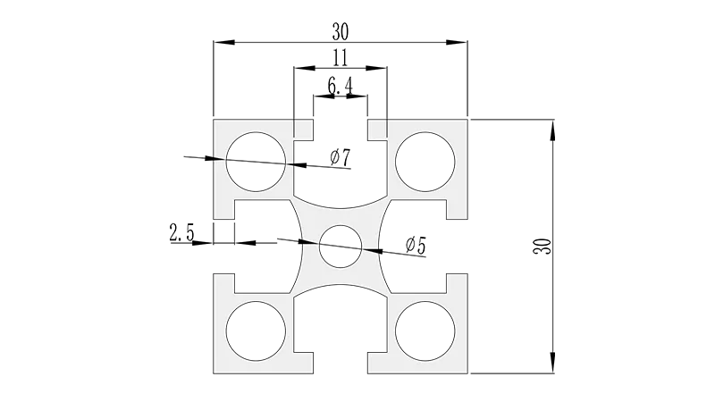
If you've ever walked through a manufacturing plant, a workshop, or even a modern office, you've probably seen structures built with sleek, modular aluminum profiles. These lightweight yet sturdy frameworks are the backbone of everything from workbenches and material racks to assembly lines and lean system setups. Among the most widely used profiles is the 3030 National Standard Profile A —a versatile 30mm x 30mm aluminum extrusion that balances strength, cost, and adaptability. But here's the thing: no matter how well-designed these structures look, their true value lies in one critical factor: load capacity. Build a workbench with 3030 profiles that can't support the tools and materials it's meant to hold, and you're looking at wobbly surfaces, damaged equipment, or worse, safety hazards. So whether you're a small business owner building a custom workbench or a plant manager optimizing a lean system, knowing how to calculate the load capacity of 3030 National Standard Profile A structures isn't just a "nice-to-know"—it's essential.
In this guide, we'll break down the process step by step, demystifying the engineering jargon and focusing on practical, real-world applications. We'll cover the key factors that influence load capacity, walk through the math (don't worry, it's simpler than it sounds), and even include a hands-on example with a table to illustrate how different variables affect results. Along the way, we'll touch on critical elements like aluminum profile accessories (those small but mighty connectors and brackets that hold everything together) and how they impact structural integrity. By the end, you'll have the knowledge to design 3030 Profile A structures that are not only functional but also safe and reliable—whether you're building a single workbench or an entire production line.
What Exactly Is 3030 National Standard Profile A?
Before we dive into calculations, let's make sure we're all on the same page about the star of the show: the 3030 National Standard Profile A. At its core, this is a hollow aluminum extrusion with a square cross-section, measuring 30mm in width and 30mm in height. The "National Standard" label means it adheres to specific dimensional and material standards set by industry regulators, ensuring consistency across manufacturers. The "A" in its name typically refers to its specific cross-sectional design—often featuring T-slots along its length (those groove-like channels) that allow for easy attachment of accessories like brackets, shelves, and panels. This T-slot design is what makes aluminum profiles so modular; you can reconfigure a structure in minutes by sliding in new accessories, no welding required.
But what really matters for load capacity is what's inside that 30x30mm frame. Most 3030 National Standard Profile A extrusions are made from 6063-T5 aluminum alloy, a popular choice for structural applications. Why 6063-T5? It's lightweight (about a third the weight of steel), corrosion-resistant, and has excellent mechanical properties—specifically, a yield strength of around 160 MPa (megapascals) and a modulus of elasticity of 69 GPa (gigapascals). These numbers might sound abstract now, but they'll be crucial later when we calculate how much stress the profile can handle before bending or deforming.
Another key detail is wall thickness. While the outer dimensions are fixed at 30x30mm, the inner wall thickness can vary slightly between manufacturers (common options are 1.5mm, 2.0mm, or 2.5mm). Thicker walls mean a stiffer, stronger profile, so always check this spec before starting your design. You'll usually find it listed in the product datasheet, along with other critical metrics like section modulus—a measure of the profile's resistance to bending, which we'll explore in depth later.
Key Factors That Influence Load Capacity
Load capacity isn't just about the profile itself—it's a puzzle made up of several interconnected pieces. Ignore one, and your calculations could be way off. Let's break down the most important factors:
1. Material Properties: It All Starts with the Aluminum
We touched on this earlier, but it's worth emphasizing: the type of aluminum alloy and its temper (heat treatment) directly impact how much load the profile can bear. 6063-T5 is standard for 3030 profiles, but if you're using a different alloy (say, 6061-T6, which has higher strength but is less malleable), your load capacity numbers will change. The yield strength (the stress at which the material starts to permanently deform) is especially critical. For 6063-T5, that's ~160 MPa—meaning if the stress on the profile exceeds this, it will bend and won't spring back. Always confirm the alloy and temper with your supplier; don't assume all 3030 profiles are the same.
2. Profile Geometry: Shape Matters
The cross-sectional shape of the 3030 Profile A plays a huge role in its load-bearing ability. Even with the same outer dimensions (30x30mm), a profile with a thicker wall or a more optimized internal structure (like reinforced ribs) will have a higher section modulus (Z). Section modulus is calculated as the moment of inertia (a measure of how the profile's mass is distributed around its axis) divided by the distance from the neutral axis to the outermost fiber. In plain English: a higher Z means the profile can resist bending better. For example, a 3030 Profile A with a 2.0mm wall thickness might have a section modulus of ~10 cm³, while a 1.5mm wall version could be closer to 8 cm³—resulting in a 20% difference in bending resistance.
3. Support Conditions: How the Profile Is Mounted
Imagine holding a ruler at both ends versus holding it by one end. In the first case, you can press down on the middle without much bending; in the second, it flops over easily. The same logic applies to 3030 profiles. Engineers categorize support conditions into three main types:
- Simply supported: The profile is supported at both ends (like a bridge between two workbench legs). This is the most common scenario for horizontal beams (e.g., the top rail of a workbench).
- Fixed support: The profile is rigidly attached at both ends, preventing rotation (think of a beam bolted to a wall at both ends). This adds stiffness and increases load capacity.
- Cantilever: The profile is supported at only one end (like a shelf sticking out from a wall). This is the weakest setup, as the unsupported end will bend significantly under load.
Your support condition determines the "bending moment" (the force that causes bending) acting on the profile, which directly affects stress and deflection.
4. Load Distribution: Uniform vs. Point Loads
How is the weight spread across the profile? A uniform load (e.g., a sheet of plywood covering the entire surface of a workbench) distributes weight evenly, reducing peak stress. A point load (e.g., a heavy machine placed directly in the middle of the workbench) concentrates stress at a single spot, making the profile more likely to bend. For example, a 100kg uniform load on a 1-meter simply supported beam will create less bending stress than a 100kg point load in the center.
5. Joint Strength: Don't Overlook the Accessories
Even the strongest profile will fail if its connections are weak. This is where aluminum profile accessories come into play—things like corner codes, T-slot nuts, bolts, and brackets. For instance, using a cheap plastic bracket to connect two 3030 profiles might save money upfront, but it could snap under load, causing the entire structure to collapse. When calculating load capacity, always account for the strength of the joints. Most reputable suppliers provide load ratings for their accessories (e.g., "this 3060 aluminum angle yard can handle 500N of shear force"), so check those specs and ensure they align with your beam's calculated stress.
Step-by-Step: Calculating Load Capacity
Now, let's put this all together. We'll focus on the most common scenario: a simply supported 3030 National Standard Profile A beam with a uniform load (e.g., the top of a workbench). We'll calculate two key metrics: maximum allowable load (to avoid permanent deformation) and deflection (how much the beam bends under load—even if it doesn't break, excessive deflection can make a workbench unusable).
Step 1: Gather Your Data
First, collect the following information (you can find most of this in the profile's datasheet or by asking your supplier):
- Yield strength (σ_yield): For 6063-T5, ~160 MPa (160,000,000 Pa)
- Modulus of elasticity (E): For aluminum, ~69 GPa (69,000,000,000 Pa)
- Section modulus (Z): Let's use a common value for 3030 Profile A with 2.0mm walls: ~10 cm³ (10,000 mm³)
- Span length (L): The distance between supports (e.g., 1000mm for a 1-meter workbench top)
- Maximum allowable deflection (δ_max): Typically, 1/200 to 1/300 of the span length (e.g., for L=1000mm, δ_max = 1000/250 = 4mm)
Step 2: Calculate Maximum Bending Stress
For a simply supported beam with a uniform load (w, in N/m), the maximum bending moment (M_max) occurs at the center and is given by:
M_max = (w × L²) / 8
Bending stress (σ) is then calculated as:
σ = M_max / Z
To ensure the profile doesn't yield, we set σ ≤ σ_yield. Rearranging to solve for w:
w ≤ (σ_yield × Z × 8) / L²
Plugging in the numbers:
w ≤ (160,000,000 Pa × 10,000 mm³ × 8) / (1000 mm)²
Wait—units matter! Convert everything to meters and cubic meters to keep Pa (N/m²) consistent:
Z = 10,000 mm³ = 10,000 × 10⁻⁹ m³ = 1 × 10⁻⁵ m³
L = 1 m
w ≤ (160,000,000 N/m² × 1 × 10⁻⁵ m³ × 8) / (1 m)² = (12,800 N·m) / 1 m² = 12,800 N/m
This means the beam can handle a uniform load of 12,800 N per meter (or ~1,280 kg/m, since 1 N = ~0.102 kg). For a 1-meter span, that's 12,800 N total (~1,280 kg). But wait—this is just the bending stress limit. We also need to check deflection.
Step 3: Calculate Deflection
The formula for maximum deflection (δ_max) of a simply supported beam under uniform load is:
δ_max = (5 × w × L⁴) / (384 × E × I)
Where I is the moment of inertia (I = Z × c, where c is the distance from the neutral axis to the outer fiber. For a symmetric profile like 3030, c = 15mm (half the height). So I = Z × c = 10,000 mm³ × 15 mm = 150,000 mm⁴ = 150,000 × 10⁻¹² m⁴ = 1.5 × 10⁻⁷ m⁴).
We want δ_max ≤ 4mm (0.004m). Rearranging to solve for w:
w ≤ (δ_max × 384 × E × I) / (5 × L⁴)
Plugging in the numbers:
w ≤ (0.004 m × 384 × 69,000,000,000 Pa × 1.5 × 10⁻⁷ m⁴) / (5 × (1 m)⁴)
w ≤ (0.004 × 384 × 69e9 × 1.5e-7) / 5 ≈ (0.004 × 384 × 10,350) / 5 ≈ (160,512) / 5 ≈ 32,102 N/m
Deflection allows for a higher load (~32,102 N/m) than bending stress, so the bending stress limit (12,800 N/m) is the governing factor here. Thus, our 1-meter 3030 Profile A beam can safely support ~12,800 N (~1,280 kg) uniformly distributed.
Step 4: Account for Safety Factor
Engineers always add a safety factor (SF) to account for uncertainties (e.g., material variations, unexpected loads). A typical SF for non-critical applications is 1.5–2.0. Using SF = 2.0:
Safe load = Calculated load / SF = 12,800 N / 2 = 6,400 N (~640 kg) for a 1-meter span.
Practical Example: How Span Length Affects Load Capacity
To see how span length impacts load capacity, let's calculate the safe load for different spans (using the same 3030 Profile A, SF=2.0). The results are summarized in the table below:
| Span Length (L) | Section Modulus (Z) | Bending Stress Limit (w_bend) | Deflection Limit (w_deflect) | Governing Load (min(w_bend, w_deflect)) | Safe Load (Governing Load / SF=2) |
|---|---|---|---|---|---|
| 500 mm (0.5m) | 10,000 mm³ | 51,200 N/m (~5,120 kg/m) | 513,632 N/m (~51,363 kg/m) | 51,200 N/m | 25,600 N (~2,560 kg for 0.5m span) |
| 1000 mm (1m) | 10,000 mm³ | 12,800 N/m (~1,280 kg/m) | 32,102 N/m (~3,210 kg/m) | 12,800 N/m | 6,400 N (~640 kg for 1m span) |
| 1500 mm (1.5m) | 10,000 mm³ | 5,689 N/m (~569 kg/m) | 5,197 N/m (~519 kg/m) | 5,197 N/m | 2,598 N (~260 kg for 1.5m span) |
| 2000 mm (2m) | 10,000 mm³ | 3,200 N/m (~320 kg/m) | 1,254 N/m (~125 kg/m) | 1,254 N/m | 627 N (~63 kg for 2m span) |
*Note: Loads are approximate and based on 6063-T5 aluminum, 2.0mm wall thickness, and simply supported conditions. Always verify with your specific profile's datasheet.
The takeaway? Load capacity drops dramatically as span length increases. A 2-meter span can only support ~63 kg safely—less than half the weight of a small refrigerator! This is why longer workbenches often use additional supports (e.g., a center leg) to reduce span length and boost load capacity.
The Role of Aluminum Profile Accessories in Load Capacity
We've focused a lot on the profile itself, but aluminum profile accessories are the unsung heroes (or potential weak links) in your structure. Even if your beam calculations check out, a flimsy joint can cause the entire system to fail. Let's look at the most critical accessories and how to factor them in:
Corner Codes and Connectors
These small metal brackets (like 3060 aluminum angle yards or 20# aluminum corner codes) are used to join profiles at 90° angles. They're typically secured with T-slot nuts and bolts. The key here is shear strength—the force that tries to slide the connector apart. A typical 3030 corner code might have a shear strength of 5000 N per bolt. If you use two bolts per corner, that's 10,000 N of shear resistance. Compare this to the beam's load: if your workbench top exerts 6,400 N of force on the legs, the corner codes (10,000 N capacity) are more than sufficient. But if you skimp on bolts (using one instead of two), you cut that capacity in half, creating a weak point.
T-Slot Nuts and Bolts
These fasteners hold accessories to the profile's T-slots. The bolt's diameter and thread strength matter here. A M6 bolt (common for 3030 profiles) has a tensile strength of ~20,000 N. If you're using a single M6 bolt to attach a bracket, it can handle ~20,000 N in tension—but if the load is shear (sliding), that drops to ~10,000 N. Always use the recommended bolt size for your accessory, and don't overtighten (this can strip the T-slot or damage the nut).
End Caps and Reinforcements
While end caps don't add strength, internal reinforcements (like inserting a solid aluminum rod into the profile's hollow core) can increase the moment of inertia (I), boosting stiffness and reducing deflection. This is a handy trick for cantilevered sections (e.g., a shelf sticking out from a workbench) where deflection is a problem.
Common Mistakes to Avoid
Even seasoned designers make errors when calculating load capacity. Here are the top pitfalls to watch for:
- Ignoring dynamic loads: If you're placing heavy equipment that vibrates (e.g., a drill press) on a workbench, the dynamic load (due to vibration) can be 2–3x the static load. Add a higher safety factor (3.0+) for dynamic applications.
- Overlooking joint weakness: As we saw, accessories can fail before the profile. Always check accessory load ratings and ensure they exceed the beam's calculated load.
- Using the wrong support condition: Assuming a beam is "fixed" when it's actually simply supported will lead to overestimating load capacity. If your connections aren't rigid (e.g., using loose bolts), treat the beam as simply supported.
- Forgetting environmental factors: Aluminum's properties can change with temperature (it weakens slightly in extreme heat). If your structure will be used in a hot factory or cold warehouse, adjust your calculations accordingly.
Conclusion: Build with Confidence
Calculating the load capacity of 3030 National Standard Profile A structures might seem intimidating at first, but it boils down to understanding a few key principles: material properties, support conditions, load distribution, and the role of accessories. By following the steps outlined here—gathering data, calculating bending stress and deflection, checking accessory ratings, and applying a safety factor—you can design structures that are strong, safe, and tailored to your needs. Whether you're building a simple workbench or a complex lean system, this knowledge ensures your aluminum profiles work as hard as you do—supporting your operations without compromise.
Remember, when in doubt, consult your supplier or a structural engineer. Most aluminum profile suppliers have technical teams who can help verify your calculations, and many even offer free design tools or software to simplify the process. With the right approach, you'll transform those 30mm x 30mm extrusions into reliable, high-performance structures that stand the test of time.