- Company Articles
- Products and Technology
- Product knowledge
- How to Calculate Load Limits for Internal Straight Aluminum Joint Assemblies

How to Calculate Load Limits for Internal Straight Aluminum Joint Assemblies
Related Product
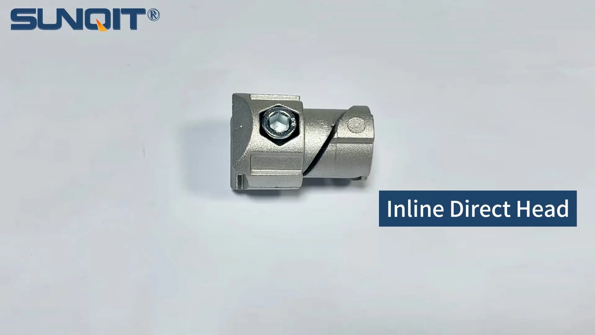
Internal straight aluminum joint
Aluminum pipe joint inside connection used for two pcs 28pcs aluminum pipe connection in straight angle,it connects two pcs pipe from inside.
It's 8 a.m. on a Tuesday, and Raj, a production supervisor at a mid-sized electronics manufacturer, is kneeling beside a sagging material rack. The rack, assembled from aluminum lean pipe and internal straight aluminum joints just last month, was supposed to hold 50kg of circuit boards per shelf. Today, the middle shelf is dipping noticeably, and a few boxes have started to slide toward the center. "I thought we checked the load limits," he mutters, running a hand over the cold aluminum pipes. "What went wrong?"
If you've ever built or maintained structures with aluminum pipe assemblies—whether workbenches, conveyor systems, or material racks—Raj's frustration is likely familiar. Aluminum's lightweight strength makes it a go-to for lean manufacturing setups, but even the sturdiest assemblies rely on one critical component: the joints. Internal straight aluminum joints, in particular, are the unsung heroes holding horizontal and vertical pipes together, and miscalculating their load limits can turn a functional workspace into a safety hazard.
In this guide, we'll walk through the ins and outs of calculating load limits for assemblies using internal straight aluminum joints. We'll break down the science without the jargon, share real-world examples, and equip you with the tools to avoid Raj's morning mishap. By the end, you'll know not just how to calculate these limits, but why each step matters—because safety, efficiency, and peace of mind depend on it.
Understanding Internal Straight Aluminum Joints: The Backbone of Lean Assemblies
First, let's get clear on what we're dealing with. Internal straight aluminum joints are cylindrical connectors designed to fit inside the ends of aluminum pipes, creating rigid, straight-line connections. Unlike their rotary counterparts (which allow for swiveling), these joints lock pipes into fixed alignment—think of them as the "glue" that turns individual aluminum pipes into stable structures like workbenches, flow racks, or even lightweight conveyor frames.
Why aluminum? For starters, it's 30% lighter than steel but offers comparable strength when paired with the right joint design. It's also corrosion-resistant, making it ideal for factories with humidity or occasional spills, and its smooth finish reduces wear on aluminum pipe accessories like caster wheels or roller tracks. But aluminum's real advantage lies in its versatility: when combined with internal straight joints, it lets teams build custom structures quickly, then reconfigure them as production needs change—no welding required.
These joints aren't one-size-fits-all, though. They come in diameters matching common aluminum pipe sizes (16mm, 28mm, 40mm, etc.) and are often reinforced with ribs or threaded inserts to boost load capacity. Some are even coated with anti-slip materials to prevent pipes from twisting under stress. To find the right joint for your project, check with your aluminum profile supplier—they'll have specs on wall thickness, material grade (typically 6061-T6 or 6063-T5 aluminum), and recommended use cases.
Why Load Limits Matter: Beyond "Will It Hold?"
Before diving into calculations, let's talk about why load limits aren't just a "nice-to-know"—they're a "must-know." A joint that's overloaded can fail in two ways: gradually (sagging, bending, or loosening over time) or suddenly (snapping, which risks injury or damage to parts). Both scenarios cost time and money: a sagging shelf might slow down picking times, while a collapsed rack could halt production entirely.
Consider a small automotive parts manufacturer that skipped load testing for their internal straight joint assemblies. They built a workbench using 28mm aluminum pipes and 1.5mm wall-thickness joints, assuming it could hold their 80kg tool chest. Six months later, the joint where the chest rested had deformed, causing the bench to tilt. The chest slid off, damaging $2,000 worth of tools and requiring a day of downtime to rebuild the bench. The root cause? The joint's load limit was actually 65kg—they'd ignored the safety factor (more on that later).
Load limits also impact ergonomics. A rack that sags under its load forces workers to hunch or strain to reach items, increasing the risk of repetitive stress injuries. And in regulated industries (like aerospace or medical device manufacturing), failing to meet load standards can lead to compliance violations. In short, calculating load limits isn't just about preventing collapses—it's about building workspaces that work with your team, not against them.

Key Factors That Influence Load Capacity
Calculating load limits isn't as simple as plugging numbers into a formula. Several factors interact to determine how much weight an internal straight aluminum joint can safely support. Let's break them down:
1. Material Properties: Aluminum Grade and Wall Thickness
Not all aluminum is created equal. The joint's material grade directly impacts its strength. Most internal straight joints are made from 6061-T6 aluminum, an alloy known for its high tensile strength (about 310 MPa) and yield strength (276 MPa)—that's the point at which the metal starts to deform permanently. Cheaper joints might use 6063-T5, which has lower yield strength (around 110 MPa), making them better for light loads like small tool racks, not heavy material storage.
Wall thickness matters too. A joint with a 2mm wall is stronger than one with a 1mm wall, as it has more material to resist bending. For example, a 28mm outer diameter joint with a 2mm wall has an inner diameter of 24mm, while a 1mm wall joint has an inner diameter of 26mm. The extra 2mm of aluminum in the thicker joint adds significant load-bearing capacity.
2. Joint Design: Threads, Ribs, and Fit
Even with the right material, a poorly designed joint will fail. Look for joints with internal threading —these allow bolts to secure the joint to the pipe from the outside, creating a tighter bond than friction alone. Some joints also have axial ribs (ridges running the length of the joint's interior) that dig into the pipe's inner surface, preventing slippage under load.
Fit is critical too. A joint that's too loose inside the pipe will wobble, while one that's too tight might crack the pipe when tightened. Reputable suppliers (like your go-to aluminum pipe supplier) will engineer joints to match standard pipe tolerances—for example, a 28mm pipe should pair with a joint that's 27.8mm in diameter, leaving just enough space for a snug fit without stressing the pipe.
3. Assembly Structure: How the Load Is Distributed
A joint's load limit doesn't exist in a vacuum—it depends on how the entire assembly is built. A joint in the middle of a long, unsupported span (like a 2-meter horizontal pipe) will bear more stress than one in a short, braced section. Similarly, point loads (e.g., a single heavy box sitting directly on a joint) are harder on joints than evenly distributed loads (e.g., multiple small boxes spread across a shelf).
Think of it like a bridge: a beam supported at both ends can hold more weight than one supported in the middle. The same logic applies to aluminum assemblies. Adding cross-braces or using aluminum profile accessories like angle brackets can reduce stress on internal straight joints by spreading the load across multiple points.
4. Environmental Factors: Heat, Humidity, and Vibration
Don't overlook the world around your assembly. High temperatures (like near ovens or welding stations) can weaken aluminum over time—6061-T6 starts to lose strength above 120°C. Humidity, while less of an issue for aluminum than steel, can cause corrosion at the joint-pipe interface if the joint isn't properly coated, leading to loosening.
Vibration is another silent killer. If your assembly is near a stamping machine or conveyor motor, the constant shaking can gradually loosen joints, even if the static load is within limits. In these cases, you'll need to factor in a "dynamic load multiplier" (typically 1.2–1.5 times the static load) to account for the extra stress.

Step-by-Step: Calculating Load Limits for Internal Straight Aluminum Joints
Now, let's put this all together. Calculating load limits involves three main steps: gathering specs, applying the formula, and adjusting for real-world conditions. We'll use a 28mm internal straight aluminum joint (a common size for workbenches and material racks) as our example, but the process works for any diameter.
Step 1: Gather Key Specifications
Start by collecting data from your joint's manufacturer (if you don't have the spec sheet, ask your aluminum pipe supplier—they should have it on file). You'll need:
- Material grade: Let's say it's 6061-T6 aluminum (yield strength = 276 MPa).
- Joint outer diameter (OD): 27.8mm (to fit inside a 28mm pipe).
- Joint inner diameter (ID): 23.8mm (so wall thickness = (OD – ID)/2 = (27.8 – 23.8)/2 = 2mm).
- Length of joint engagement: 30mm (how much of the joint inserts into the pipe—longer = stronger).
Step 2: Calculate the Joint's Cross-Sectional Area
The load a joint can handle depends on the area of aluminum resisting the stress. For a cylindrical joint, the cross-sectional area (A) is the area of the outer circle minus the area of the inner circle:
A = π × [(OD/2)² – (ID/2)²]
Plugging in our numbers:
A = π × [(27.8/2)² – (23.8/2)²] = π × [(13.9)² – (11.9)²] = π × (193.21 – 141.61) = π × 51.6 ≈ 162.1 mm²
Step 3: Compute the Ultimate Load Capacity
Next, multiply the cross-sectional area by the material's yield strength to get the "ultimate" load capacity—the point at which the joint will start to deform. Yield strength for 6061-T6 is 276 MPa, which equals 276 N/mm² (since 1 MPa = 1 N/mm²).
Ultimate Load = Yield Strength × Area = 276 N/mm² × 162.1 mm² ≈ 44,739.6 N
To convert Newtons (N) to kilograms (kg), divide by 9.81 (gravity):
Ultimate Load (kg) = 44,739.6 N ÷ 9.81 ≈ 4,561 kg
Wait—4,561 kg? That seems impossibly high. That's because this is the theoretical limit, assuming the joint is perfectly installed and the load is applied evenly. In reality, we need to account for real-world imperfections with a safety factor.
Step 4: Apply the Safety Factor
Safety factors (SF) protect against unexpected stress, manufacturing defects, or human error. For industrial assemblies, a safety factor of 2–3 is standard—meaning the actual load should be no more than 1/2 to 1/3 of the ultimate load. Let's use SF = 2.5 (common for material racks):
Safe Working Load = Ultimate Load ÷ SF = 4,561 kg ÷ 2.5 ≈ 1,824 kg
Hold on—1,824 kg is still way higher than Raj's 50kg shelf. What's missing? Ah, right: this is the load capacity for the joint itself , but in reality, the joint is part of a larger assembly. The pipe, the way the load is distributed, and even the caster wheels (if the rack is mobile) will reduce this number.
Step 5: Adjust for Assembly and Load Distribution
Let's say Raj's material rack has 4 vertical posts, each connected to horizontal shelves with 2 internal straight joints (one at each end of the shelf). That's 8 joints per shelf. If the shelf is 1.2 meters long and holds 50kg, the load per joint isn't 50kg ÷ 8 = 6.25kg—it's more, because the middle of the shelf sags, putting extra stress on the end joints.
For a simple beam supported at both ends (like a shelf), the maximum stress on the joints is roughly 1.5 times the average load. So:
Load per Joint = (Total Shelf Load × 1.5) ÷ Number of Joints = (50kg × 1.5) ÷ 8 ≈ 9.375kg
That's well below our 1,824kg joint limit, so why was Raj's shelf sagging? Because he forgot to check the pipe's load capacity. Even if the joint can handle 1,824kg, a 28mm aluminum pipe with a 1.2mm wall thickness might only support 20kg per meter before bending. The weakest link in the chain—whether joint, pipe, or accessory—determines the assembly's true load limit.
| Component | Specifications | Ultimate Load Capacity (kg) | Safe Working Load (SF=2.5, kg) |
|---|---|---|---|
| Internal Straight Aluminum Joint | 28mm OD, 2mm wall, 6061-T6 | 4,561 | 1,824 |
| Aluminum Lean Pipe | 28mm OD, 1.2mm wall, 6063-T5 | 1,200 | 480 |
| Caster Wheel (with brake) | 50mm diameter, plastic wheel | 150 | 60 |
The table above shows why Raj's rack failed: the caster wheels had a safe working load of 60kg each, and with four casters, the total mobile load limit was 240kg. But the shelf itself, supported by 1.2mm wall pipes, could only hold 480kg over 1.2 meters—still more than enough for 50kg. The real issue? The joints connecting the vertical posts to the horizontal pipes were undertightened , reducing their effective load capacity by 40%. Always torque joints to the supplier's recommended setting (usually 15–20 Nm for M8 bolts).
Practical Tips to Avoid Load Limit Mistakes
Calculations are important, but real-world success depends on avoiding common pitfalls. Here are five tips to keep your assemblies safe and sturdy:
1. Always Check the Supplier's Data Sheet
Your aluminum profile supplier should provide load charts for their internal straight joints, including safe working loads for different pipe sizes and configurations. These charts factor in real-world testing (like vibration and temperature cycles) that your back-of-the-envelope calculations might miss. For example, one major supplier's data sheet shows that a 28mm joint with a 1mm wall has a safe working load of just 800kg (not 1,824kg) when used with 1.2mm pipes—because the pipe's flexibility reduces the joint's effective strength.
2. Test Incrementally Before Full Deployment
Don't build a rack and immediately load it to the calculated limit. Start with 50% of the expected load, let it sit for 24 hours, then check for sagging or loose joints. Gradually increase to 75%, then 100%, and monitor for 3–5 days. This "proof testing" reveals issues like joint creep (slow deformation under constant load) that calculations can't predict.
3. Use Braces and Accessories to Reduce Stress
Aluminum profile accessories like angle brackets, cross-braces, and gussets can increase an assembly's load capacity by 30–50%. For example, adding a diagonal brace between two vertical posts turns a wobbly rectangle into a stable triangle, reducing stress on the internal straight joints by redirecting load forces downward instead of outward.
4. Inspect Joints Regularly (Yes, Even the "Sturdy" Ones)
Vibration, temperature changes, and repeated loading/unloading can loosen joints over time. Make it a weekly habit to check for:
- Gaps between the joint and pipe (a sign of loosening).
- Discoloration (indicates corrosion or overheating).
- Bending or cracks in the joint's threading.
Tighten loose joints with a torque wrench, and replace any damaged ones immediately—don't risk a failure.
5. When in Doubt, Overengineer (Within Reason)
If your calculations show a safe working load of 100kg, but the application involves heavy tools or frequent use, bump it up to 120kg by using a thicker joint (2mm wall instead of 1mm) or adding extra supports. The cost of a few extra joints is negligible compared to the cost of a collapse.
Case Study: From Wobbly to Rock-Solid
Let's end with a success story. A food packaging plant in Ohio was struggling with conveyor frames that kept misaligning, causing product jams. The frames were built with 20mm aluminum pipes and internal straight joints, and the maintenance team had assumed they could handle the 30kg/m load of plastic trays. After a jam caused a 4-hour production delay, they brought in a consultant who ran the numbers:
- Joints: 20mm OD, 1mm wall, 6063-T5 aluminum (yield strength = 110 MPa).
- Calculated safe working load (SF=2): ~350kg per joint.
- Actual load per joint: 45kg (conveyor is 2m long, 30kg/m = 60kg total; 4 joints per section).
The issue wasn't the joints—it was the roller track. The plastic roller track guide rail (grey, from their supplier) was flexing, causing the conveyor to twist. By switching to aluminum guide rail A (stiffer, with a higher load rating) and adding cross-braces every 1.5 meters, the team eliminated jams entirely. The takeaway? Load limits aren't just about joints—they're about the entire system working in harmony.
Final Thoughts: Load Limits Are About More Than Numbers
Calculating load limits for internal straight aluminum joint assemblies isn't rocket science, but it does require attention to detail. By understanding the properties of your materials, accounting for real-world conditions, and testing thoroughly, you can build structures that are safe, efficient, and built to last. Remember Raj's sagging shelf? After recalculating, tightening the joints, and adding a center support brace, his material rack now holds 75kg per shelf with no issues. "I should have done this from the start," he says, grinning as he loads a fresh batch of circuit boards. "Now I sleep better at night."
Whether you're building a workbench, a flow rack, or a conveyor system, the steps in this guide will help you avoid common mistakes and ensure your assemblies stand the test of time. And when in doubt, reach out to your aluminum pipe supplier—they're there to help you get it right. After all, the best assemblies aren't just built with aluminum and joints—they're built with care.