- Company Articles
- Products and Technology
- Product knowledge
- How to Calculate Load Requirements for End Support for Roller Track Placon Mount with Wheel

How to Calculate Load Requirements for End Support for Roller Track Placon Mount with Wheel
Related Product
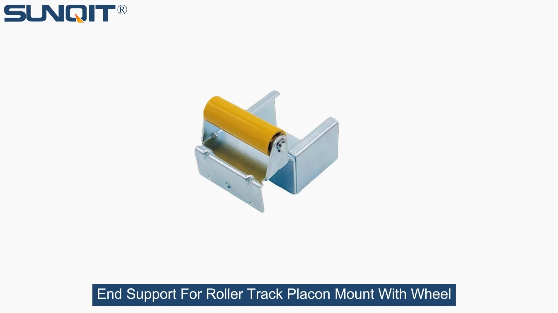
End Support for Roller Track Placon Mount with Wheel
End support for roller track placon mount with wheel,the special design with end wheel,make it with more flexible function for roller track and pipe connection and give more option for selection for building flow rack system.
In the heart of every manufacturing facility, from bustling 3C assembly lines to precision medical device workshops, there's a silent workhorse that keeps operations moving: the roller track. These systems glide components from station to station, ensuring that production flows like a well-choreographed dance. But behind that seamless movement lies a critical detail that's easy to overlook—the end support for roller track placon mount with wheel. Think about a typical day in your factory: workers load circuit boards onto the roller track, cartons of medical supplies glide toward packaging, or automotive parts transition between assembly stages. What happens if that end support isn't built to handle the load? A sudden jolt, a stuck roller, or worse—a collapse that halts production and risks worker safety. That's why getting the load calculation right isn't just a technicality; it's the backbone of reliable, efficient, and safe manufacturing.
1. Why Load Calculation Matters for End Supports: More Than Just Numbers
Before diving into formulas and figures, let's talk about why this step is non-negotiable. End supports with wheels aren't just metal brackets—they're the guardians of your roller track's integrity. Here's why getting their load capacity right matters:
- Safety First, Always : The most obvious reason, but worth emphasizing. An underrated end support can bend or fail under heavy loads, putting workers at risk of injury from falling materials or equipment damage. In industries like medical manufacturing, where precision and sterility are critical, even a small disruption can compromise product quality.
- Uninterrupted Production Flow : A stuck roller track because of a weak end support doesn't just stop one workstation—it creates a ripple effect. Delays stack up, deadlines get missed, and your team spends valuable time troubleshooting instead of building. For facilities running 24/7, those minutes lost translate to significant costs.
- Long-Term Cost Savings : Investing time in accurate load calculation upfront prevents costly do-overs. Imagine installing a roller track system only to realize the end supports can't handle peak loads—you'd need to replace parts, halt production, and absorb extra expenses. Getting it right the first time aligns with the lean philosophy of "sustainable improvement" by avoiding waste.
Pro Tip: End supports with wheels are unique because they combine static load (the weight of stationary materials) and dynamic load (the force when materials start moving, stop, or shift). This dual responsibility makes their load requirements more complex than fixed supports—but also more critical to get right.
2. Key Factors That Shape Load Requirements
Calculating load requirements isn't a one-size-fits-all process. It depends on the specific demands of your operation. Let's break down the factors that will influence your end support's load capacity needs:
a. Material Weight and Distribution
Start with the basics: What's actually moving on your roller track? A 3C assembly line might transport lightweight circuit boards (500g each), while an automotive plant could move steel components weighing 10kg or more. But it's not just individual item weight—how many items are on the track at once? A fully loaded roller track with 20 circuit boards vs. 5 steel parts creates very different load scenarios. Distribution matters too: Are materials spread evenly, or clustered at one end? Uneven weight can strain the end support disproportionately.
b. Dynamic vs. Static Load: The Hidden Force
Static load is straightforward—the weight when everything is still. Dynamic load, though, is the wildcard. When a worker pushes a cart onto the roller track, or a motorized conveyor starts moving, there's an initial force (acceleration) that adds stress. Similarly, when materials stop suddenly at the end support, deceleration creates a "shock load." For example, a 10kg part sliding at 0.5m/s might exert double its static weight on the end support when it hits the stop. Ignoring dynamic load is like building a bridge for cars but forgetting to account for trucks—it's only a matter of time before it fails.
c. Environmental and Usage Conditions
Your factory's environment plays a role too. Is the roller track in a temperature-controlled medical lab, or a dusty automotive workshop? Humidity, corrosion, and debris can weaken materials over time, meaning you might need a higher load capacity to account for wear. Usage frequency matters as well: A roller track used 8 hours a day, 5 days a week, will experience more fatigue than one used intermittently. Think of it like a pair of shoes—daily use wears them out faster than occasional wear, so you'd pick a sturdier pair for daily commutes.
d. Compatibility with Your Lean System
The end support doesn't work alone—it's part of a larger ecosystem, often integrated with lean pipe structures, workbenches, and conveyors. For example, if your roller track is mounted on a lean pipe frame, the end support must align with the frame's load capacity to avoid weak links. A mismatch here—like pairing a heavy-duty roller track with a lightweight lean pipe frame—undermines the entire system's reliability.
| Factor | Example Scenario | Impact on Load Requirement |
|---|---|---|
| Material Weight | 3C components (0.5kg each) vs. Automotive parts (15kg each) | Higher individual weight increases total load |
| Dynamic Load | Manual pushing vs. motorized conveyor acceleration | Motorized systems add 30-50% to static load |
| Usage Frequency | 8-hour daily use vs. occasional batch processing | Daily use requires 10-20% higher load capacity for durability |
| Lean System Integration | Mounted on aluminum lean pipe vs. steel frame | Aluminum frames may require end supports with lower max load to match frame limits |

2. Step-by-Step Guide to Calculating Load Requirements
Now that we've covered the "why" and "what," let's get to the "how." Calculating load requirements for your end support with wheel doesn't require an engineering degree—just a systematic approach and attention to detail. Let's walk through the process step by step.
Step 1: Define the Maximum Material Weight per Unit
Start by listing all materials that will use the roller track. For each, note the maximum weight of a single unit. If you're unsure, check product specs or weigh a sample. For example:
- 3C assembly line: Circuit board assemblies (max 1.2kg each)
- Medical device workshop: Sterile tool kits (max 2.5kg per carton)
Write this down as W (weight per unit) .
Step 2: Determine the Maximum Number of Units on the Track
Next, figure out how many units will be on the roller track at once. Measure the track length (L) and the space each unit occupies (S). The number of units (N) = L/S. For example, a 3-meter track with units spaced 0.3m apart holds 10 units. If workers sometimes stack units (e.g., two cartons side by side), multiply by the stacking factor (e.g., 2 for double stacking).
Now calculate Total Static Load (TSL) = W × N .
Step 3: Account for Dynamic Load
Dynamic load (DL) is the extra force from movement. Use this simple formula based on how materials are loaded/unloaded:
- Manual pushing/pulling: DL = TSL × 1.3 (30% increase)
- Motorized conveyor: DL = TSL × 1.5 (50% increase)
- Heavy/irregular items (e.g., large automotive parts): DL = TSL × 1.7 (70% increase)
Example: For a manual 3C line with TSL = 12kg (10 units × 1.2kg), DL = 12kg × 1.3 = 15.6kg.
Step 4: Add the Roller Track and Placon Mount Weight
Don't forget the weight of the roller track itself! A typical 3-meter aluminum roller track with placon mounts weighs ~8kg. Add this to the dynamic load to get Total Load (TL) = DL + Track Weight .
Example: 15.6kg (DL) + 8kg (track) = 23.6kg.
Step 5: Apply the Safety Factor
No calculation is complete without a safety buffer. Manufacturing environments are unpredictable—materials might be heavier than expected, or the track might be used more frequently. A safety factor (SF) of 1.5–2.0 is standard. For critical applications (e.g., medical devices, heavy machinery), use SF = 2.0.
Required Load Capacity (RLC) = TL × SF
Example: 23.6kg × 1.5 = 35.4kg. So the end support must handle at least 35.4kg.
Step 6: Verify with End Support Specifications
Finally, check the manufacturer's specs for the end support for roller track placon mount with wheel. Ensure its rated load capacity exceeds your RLC. For our example, a support rated for 40kg would be ideal—providing extra room for unexpected loads.
Quick Formula Cheat Sheet: RLC = (W × N × Dynamic Factor + Track Weight) × Safety Factor

3. Real-World Case Study: Solving Load Issues in a 3C Assembly Line
Let's put this into practice with a scenario we've helped resolve: A 3C manufacturer was experiencing frequent jams in their roller track system, particularly at the end support. Workers reported that when loading more than 8 circuit board assemblies, the end support would "sag," causing rollers to stick. Production slowed by 15% as teams stopped to fix jams.
Our team started by calculating the load using the steps above:
- W = 1.5kg (heavier than initial estimate, as some boards included batteries)
- N = 12 units (track length 3.6m, unit spacing 0.3m)
- TSL = 1.5kg × 12 = 18kg
- Dynamic Factor = 1.3 (manual pushing)
- DL = 18kg × 1.3 = 23.4kg
- Track Weight = 9kg (aluminum roller track with plastic guides)
- TL = 23.4kg + 9kg = 32.4kg
- Safety Factor = 1.5 → RLC = 32.4kg × 1.5 = 48.6kg
The existing end support was rated for only 30kg—way below the required 48.6kg. By upgrading to a heavy-duty end support with wheel (rated 60kg), the sagging stopped, jams disappeared, and production returned to full speed. The fix not only improved efficiency but also reduced worker frustration—proving that load calculation directly impacts daily operations.

4. Common Mistakes to Avoid
Even with the right steps, miscalculations happen. Here are the pitfalls we see most often:
- Underestimating Dynamic Load : Many teams only calculate static load, forgetting that movement doubles stress. A 10kg static load can feel like 20kg when sliding fast.
- Ignoring Track Weight : The roller track itself adds significant weight, especially for longer systems. Skipping this step leads to underrated supports.
- Using the Wrong Safety Factor : Cutting corners on safety (e.g., SF = 1.0) saves money upfront but risks catastrophic failure later.
- Mismatching with Lean Pipe Systems : If your roller track is mounted on a lean pipe frame, ensure the frame's load capacity matches the end support. A 100kg support on a 50kg frame is useless.
5. Choosing the Right End Support: Beyond Load Capacity
Once you've calculated the required load, it's time to pick the end support. Look for these features to ensure compatibility and longevity:
- Material Quality : Aluminum or steel supports are best for durability. Aluminum is lighter (great for lean systems) but steel offers higher strength for heavy loads.
- Wheel Design : For smooth movement, choose wheels with ball bearings and non-slip treads (especially important for ESD workbenches where static control matters).
- Adjustability : Supports with height/angle adjustment accommodate uneven floors, ensuring the roller track stays level.
- Lean Compatibility : Look for supports designed to work with standard lean pipe sizes (e.g., 28mm diameter) for easy integration with existing workbenches and frames.
6. Final Thoughts: Load Calculation as Part of Your Lean Journey
Calculating load requirements for end support for roller track placon mount with wheel might seem like a small detail, but it's a big part of the lean philosophy—"sustainable improvement" starts with reliability. By taking the time to get this right, you're not just building a stronger roller track; you're building a more resilient, efficient, and safe workplace. Whether you're running a 3C assembly line or a medical device workshop, the goal is the same: to keep production moving, protect your team, and avoid costly disruptions.
Remember, your roller track system is only as strong as its weakest link. Don't let that link be the end support. With the right calculations, the right parts, and a focus on real-world needs, you'll ensure that your roller track doesn't just move materials—it moves your business forward.