- Company Articles
- Products and Technology
- Product knowledge
- How to Calculate the Load Capacity of Aluminum Side Guards for Material Racks

How to Calculate the Load Capacity of Aluminum Side Guards for Material Racks
Related Product
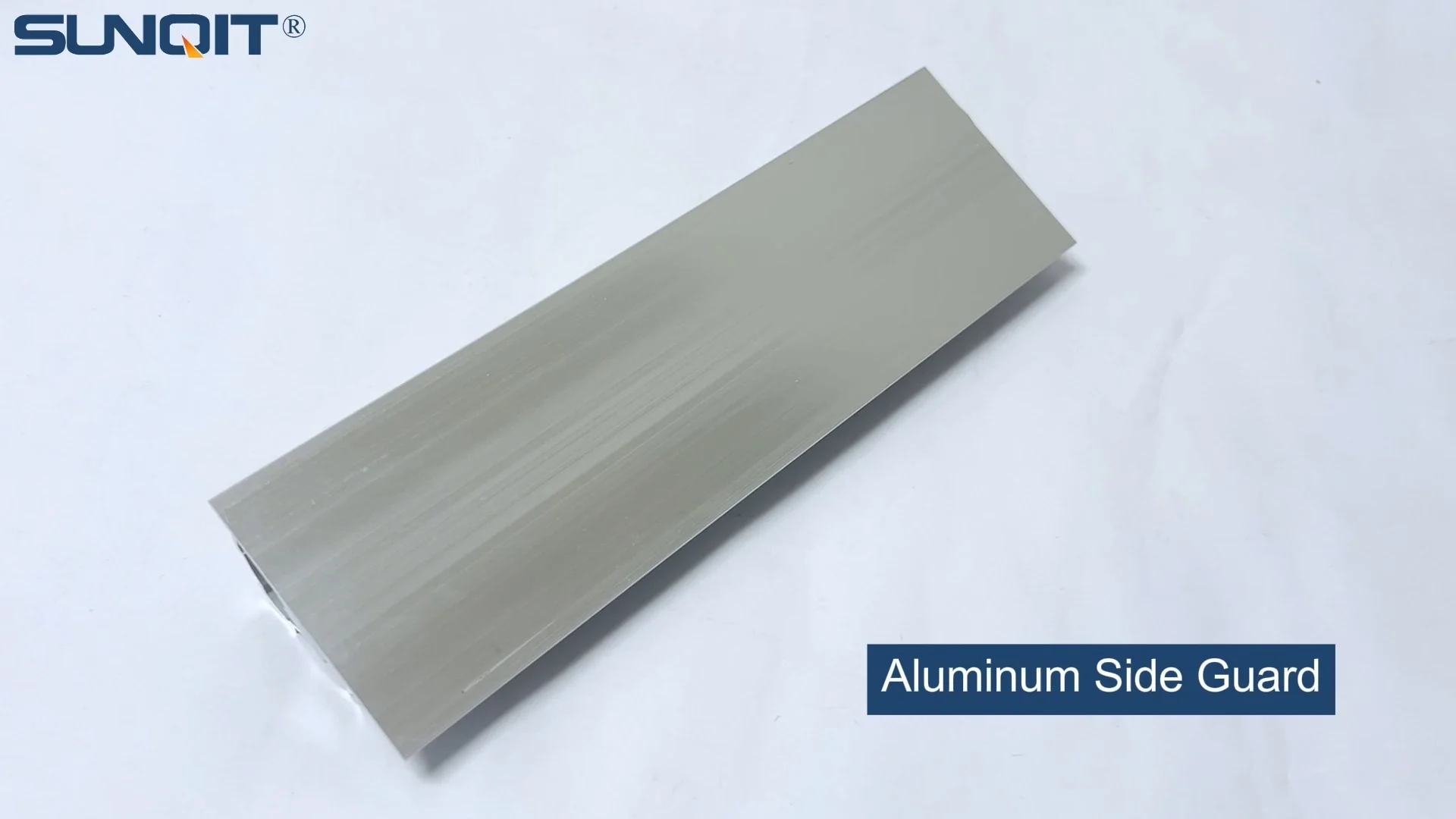
Aluminum Side Guard
Aluminum side guard, it works with a aluminum pipe or a roller track as side guard to prevent material drop,or move to wrong direction.
Understanding Aluminum Side Guards: More Than Just Metal Strips
Before we crunch numbers, let's talk about what aluminum side guards actually do. Picture a bustling warehouse: pallets stacked high, workers moving quickly, forklifts zipping by. Material racks—like the popular material rack b (3 row and 3 floor) configuration—hold everything from small components to heavy boxes. Without side guards, those items could slide or tip off the racks during loading, unloading, or even just from vibrations. That's where side guards come in: they're the vertical barriers along the edges of rack shelves, acting as a safety net to keep materials in place.
Aluminum is the material of choice here for good reason. Unlike steel, it's lightweight, making installation easier and reducing strain on the rack itself. It's also resistant to rust, which is a big plus in humid or dusty environments. But the real star is its strength-to-weight ratio: aluminum extrusion profiles (the technical term for the shaped aluminum bars used in these guards) can be engineered to be surprisingly strong while staying thin and light. When paired with aluminum profile accessories—like brackets, bolts, and corner connectors—these guards become part of a system that's both sturdy and adaptable.
But here's the catch: not all aluminum side guards are built the same. A guard meant for a small parts bin won't cut it for a shelf holding 50kg boxes. That's why calculating load capacity isn't just a "nice-to-know"—it's a safety must. Let's break down the key factors that influence how much weight an aluminum side guard can handle.
Key Factors That Determine Load Capacity
Think of load capacity as a puzzle with several pieces. Miss one, and the whole calculation falls apart. Here are the main pieces you'll need to consider:
1. The Aluminum Material Itself
Not all aluminum is created equal. The type of aluminum extrusion profile used—its alloy, temper (how it's heat-treated), and thickness—directly impacts strength. For example, 6061-T6 aluminum (a common alloy in industrial settings) has a yield strength of about 240 MPa (megapascals), meaning it starts to bend permanently when stressed beyond that point. Compare that to 5052-H32 aluminum, which has a yield strength of around 193 MPa—weaker, but more flexible. The thickness of the guard's cross-section matters too: a thicker guard (say, 4mm) will resist bending better than a thinner one (2mm), even if they're the same alloy.
2. The Guard's Dimensions
Imagine bending a ruler: a longer ruler bends easier than a short one, right? The same logic applies to side guards. The length of the guard (how much it spans between support brackets) and its height (how tall the barrier is) affect how it distributes weight. A guard that's 2 meters long with no supports in the middle will bend more under load than a 1-meter guard with the same thickness. Height matters too: a taller guard has more surface area catching the load, which can increase stress on the mounting points.
3. Mounting Method and Support
Even the strongest guard will fail if it's poorly mounted. How is the guard attached to the rack? Is it bolted directly to the aluminum profile of the rack, or just clipped on? Are there support brackets along its length, or is it only secured at the ends? For example, a guard mounted with heavy-duty aluminum profile accessories—like 90° aluminum profile connectors and high-tensile bolts—will distribute load better than one held by flimsy plastic clips. The spacing between supports (called "span") is critical here: closer supports mean less bending stress.
4. The Type of Load
Not all loads act the same way. A "point load" (like a single heavy box pressing against one spot on the guard) creates more stress than a "uniform load" (like several small boxes spread evenly along the guard). Most material racks, including material rack b, deal with uniform loads, but it's important to confirm. Also, consider dynamic vs. static loads: a load that's being pushed or pulled (dynamic) puts more stress on the guard than one sitting still (static).
5. Safety Factor
Even if your calculations say a guard can handle 100kg, you'd never want to push it to that limit. That's where the safety factor comes in—a buffer to account for unexpected stresses (like a worker accidentally bumping the guard) or slight miscalculations. A safety factor of 1.5 to 2.0 is standard in industrial design: if your calculated load capacity is 100kg, multiply by 1.5, and the guard should only be used for loads up to ~67kg.

Step-by-Step Calculation: From Specs to Safety
Now, let's put this all together with a real-world example. We'll use a common scenario: calculating the load capacity of an aluminum side guard for the middle shelf of a material rack b (3 row and 3 floor). Let's assume the shelf is 1.2 meters long, and the guard is made from a standard aluminum extrusion profile—let's say 20mm thick, 150mm tall, and made of 6061-T6 aluminum. Here's how to do it:
Step 1: Define the Load Requirements
First, figure out what the guard needs to withstand. For material rack b, each shelf might hold boxes weighing up to 30kg each, with 2-3 boxes per shelf. The worst-case scenario? A box sliding hard against the guard, exerting a horizontal force. Engineers often estimate this force as 20-30% of the box's weight (since sliding friction is lower than static). For a 30kg box, that's 6-9kg of horizontal force. If two boxes slide at once, we're looking at ~18kg of force spread along the guard.
Step 2: Gather Material Properties
We need two key numbers for the aluminum extrusion profile: yield strength (σ_yield) and modulus of elasticity (E, a measure of stiffness). For 6061-T6 aluminum:
- σ_yield = 240 MPa (240,000,000 Pascals)
- E = 69 GPa (69,000,000,000 Pascals)
Step 3: Calculate the Moment of Inertia (I)
The moment of inertia (I) measures how the guard's cross-section resists bending. For a rectangular guard (the most common shape), the formula is I = (width × height³) / 12 . Our guard is 20mm wide (0.02m) and 150mm tall (0.15m), so:
I = (0.02m × (0.15m)³) / 12 = (0.02 × 0.003375) / 12 = 0.0000675 / 12 = 0.000005625 m⁴
Step 4: Calculate Bending Moment (M)
The bending moment is the force that causes the guard to bend. For a guard mounted at both ends (like between two rack posts), the maximum bending moment for a uniformly distributed load is M = (w × L²) / 8 , where w is the load per meter, and L is the guard length. Our total load is 18kg (~180 Newtons, since force = mass × gravity). Spread over 1.2m, w = 180N / 1.2m = 150N/m. L = 1.2m, so:
M = (150N/m × (1.2m)²) / 8 = (150 × 1.44) / 8 = 216 / 8 = 27 Nm
Step 5: Determine Bending Stress (σ)
Bending stress is how much the guard is "pulled" on one side and "pushed" on the other when bent. The formula is σ = (M × c) / I , where c is the distance from the guard's neutral axis (the middle of its height) to the outer edge. For our 150mm tall guard, c = 0.075m. Plugging in the numbers:
σ = (27 Nm × 0.075m) / 0.000005625 m⁴ = 2.025 / 0.000005625 = 360,000 Pa = 0.36 MPa
Wait—that's way lower than the yield strength of 240 MPa! Does that mean the guard can handle way more? Not exactly—we need to check deflection too.
Step 6: Check Deflection
Even if the guard doesn't break, too much bending (deflection) can let materials slip through. The maximum allowable deflection for side guards is usually L/240 (the length divided by 240). For L=1.2m, that's 1.2m / 240 = 0.005m (5mm). The deflection formula for a uniformly loaded, simply supported beam (our guard) is δ = (5 × w × L⁴) / (384 × E × I) . Plugging in the numbers:
δ = (5 × 150N/m × (1.2m)⁴) / (384 × 69,000,000,000 Pa × 0.000005625 m⁴)
= (5 × 150 × 2.0736) / (384 × 69,000,000,000 × 0.000005625)
= 1555.2 / (384 × 388,125) ≈ 1555.2 / 149,040,000 ≈ 0.0000104m (0.01mm)
That's way under 5mm—great news! The guard won't bend enough to let materials slip.
Step 7: Apply Safety Factor
Remember that buffer we talked about? Multiply the calculated stress (0.36 MPa) by a safety factor of 2.0: 0.36 MPa × 2 = 0.72 MPa. Since 0.72 MPa is still way below the 240 MPa yield strength, our guard is safe for this load.

Real-World Example: Material Rack B (3 Row and 3 Floor)
Let's Test a Thinner Guard
What if we use a thinner aluminum extrusion profile—say, 1.5mm thick instead of 2mm? Let's recalculate I: I = (0.015m × (0.15m)³)/12 = (0.015 × 0.003375)/12 ≈ 0.0000041m⁴. Bending stress becomes σ = (27 × 0.075)/0.0000041 ≈ 0.49 MPa. Deflection? δ ≈ 0.013mm. Even with a safety factor of 2, it's still safe. But if we go thinner (1mm), I drops to ~0.0000027m⁴, stress rises to ~0.74 MPa, and deflection to ~0.02mm. Still okay! Aluminum's strength here is impressive.
This example shows why aluminum extrusion profiles are so versatile: even thin ones can handle typical warehouse loads. But it also highlights the importance of checking both stress and deflection—you don't want a guard that's strong enough not to break but bends so much that boxes tip over the top.
Common Mistakes to Avoid
Calculating load capacity isn't rocket science, but it's easy to trip up. Here are pitfalls to watch for:
- Using the wrong material specs: Don't guess the yield strength! Check the manufacturer's data sheet for your aluminum extrusion profile—alloy and temper matter.
- Ignoring mounting: A guard is only as strong as its brackets. If aluminum profile accessories like bolts are loose or undersized, the guard could rip free from the rack.
- Underestimating dynamic loads: A box sliding off a forklift hits harder than one sitting still. Always account for sudden impacts.
- Skipping the safety factor: Never assume "close enough" is safe. That buffer is there to save you from miscalculations or unexpected events.
Why This Matters: Safety, Savings, and Sanity
At the end of the day, calculating load capacity is about more than just numbers. It's about keeping workers safe from falling objects, preventing costly damage to inventory, and avoiding downtime from accidents. Imagine a scenario where a side guard fails because it was too thin: a heavy box falls, injuring a worker, damaging equipment, and halting production. The cost of that mistake—both financial and human—far outweighs the time spent doing these calculations.
On the flip side, over-engineering (using a thicker, heavier guard than needed) wastes money and adds unnecessary weight to the rack. Aluminum isn't cheap, and heavier guards require stronger racks, which drives up costs further. By getting the calculation right, you strike a balance: safe, effective guards that don't break the bank.
Final Thoughts: Empowering Your Material Handling
Calculating the load capacity of aluminum side guards might seem technical, but it's a skill that pays off in spades. By understanding the factors at play—material properties, dimensions, mounting, and safety factors—you can make informed decisions about which aluminum extrusion profiles and aluminum profile accessories to use. Whether you're setting up a new material rack b (3 row and 3 floor) or upgrading an old one, this knowledge ensures your side guards do what they're supposed to: keep your warehouse safe, efficient, and running like clockwork.
So the next time you look at a material rack, take a second to appreciate those aluminum side guards. They're quiet, unassuming, and absolutely critical—and now, you know exactly how to make sure they're up to the task.
| Parameter | Value for Example (Material Rack B) | Why It Matters |
|---|---|---|
| Aluminum Alloy | 6061-T6 | Determines yield strength and stiffness (modulus of elasticity). |
| Guard Thickness | 2mm (0.02m) | Thicker = higher moment of inertia (I), better resistance to bending. |
| Guard Length (L) | 1.2m | Longer spans increase bending moment (M) and deflection (δ). |
| Load (w) | 150N/m (18kg total) | Total horizontal force from sliding materials. |
| Yield Strength (σ_yield) | 240 MPa | Maximum stress the guard can handle without permanent bending. |
| Calculated Stress (σ) | 0.36 MPa | Stress from bending; must be below σ_yield (with safety factor). |
| Deflection (δ) | 0.01mm | Must be under L/240 (5mm for 1.2m length) to prevent material slippage. |