- Company Articles
- Products and Technology
- Product knowledge
- How to Calculate the Required Number of Roller Track Placon Mount Center Support Brackets

How to Calculate the Required Number of Roller Track Placon Mount Center Support Brackets
Related Product
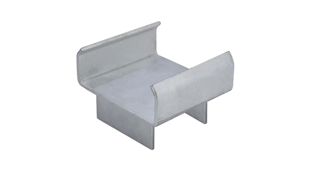
Roller Track Placon Mount Center Support Bracket
Roller track placon mount work as a connector for roller track and pipe or aluminum profile in rack syetem, it is a necessary parts in rack system which widely used in industrial plant and logistic,warehouse storage.
In the world of manufacturing and lean systems, every component plays a silent but crucial role in keeping operations running smoothly. When it comes to material handling, roller tracks are the unsung heroes—they move parts from station to station, connect workbenches, and form the backbone of efficient workflows. But even the sturdiest roller track can falter without proper support. That's where roller track placon mount center support brackets come in. These small but mighty components prevent sagging, reduce wear, and ensure your material flow stays consistent. Whether you're setting up a new lean pipe workstation or upgrading an existing conveyor line, getting the number of these brackets right isn't just a technical detail—it's a cornerstone of lean efficiency. Let's walk through how to calculate them accurately, step by step.
Understanding the Basics: What Are We Dealing With?
Before diving into calculations, let's make sure we're on the same page about the key players here. Roller tracks, often made from steel or aluminum, are the pathways that guide materials through production lines—think of them as the "highways" for your parts. Placon mount center support brackets are the "pillars" holding these highways up, mounted onto aluminum profiles (a staple in lean systems for their strength and adaptability). Without enough brackets, tracks bend under weight, slowing material flow and risking damage. Too many, and you're wasting resources—exactly what lean principles aim to avoid.
Key Roles of Center Support Brackets
- Weight Distribution: They spread the load of moving materials evenly across the track, preventing stress at weak points.
- Stability: Reduce vibration and noise, keeping tracks aligned with workbenches and conveyors.
- Longevity: Minimize wear on roller wheels and track edges, extending the life of your equipment.
Pre-Calculation Prep: Gather Your Variables
Calculating brackets isn't guesswork—it's about plugging in the right numbers. Here's what you'll need to measure or determine first:
| Variable | What It Means | How to Find It |
|---|---|---|
| Total Roller Track Length (L) | Length of the roller track section needing support | Measure from end support to end support (in meters/feet) |
| Maximum Allowable Support Spacing (S) | Distance between two consecutive brackets (center to center) | Depends on track material, load, and type (see table below) |
| Total Load (W) | Weight per meter/foot of track (including materials + track) | Check material specs + estimate average load (e.g., 30kg/m for 3C parts) |
| Track Material & Type | Steel vs. aluminum; 40mm vs. 85mm width (e.g., 40 steel roller track vs. 85 aluminum roller track) | Refer to product labels or supplier specs (e.g., "85 staggered roller track") |
| Installation Angle | Horizontal (most common) or inclined (for gravity flow racks) | Measure with a level; inclined tracks need tighter spacing |
Maximum Allowable Spacing (S) by Track Type & Load
Different tracks handle weight differently. Use this guide to find your S value (meters between brackets):
| Roller Track Type | Light Load (<20kg/m) | Medium Load (20-50kg/m) | Heavy Load (>50kg/m) |
|---|---|---|---|
| 38 Aluminum Roller Track | 1.5m | 1.2m | 0.9m |
| 40 Steel Roller Track (Yellow Wheel) | 2.0m | 1.6m | 1.2m |
| 85 Steel Roller Track | 2.5m | 2.0m | 1.5m |
| All Direction Roller Track | 1.2m | 1.0m | 0.8m |
*For inclined tracks (5°+), reduce spacing by 20% to account for gravity-induced stress.

The Calculation Formula: Step-by-Step
Now, let's put it all together. The core formula is simple, but we'll break it down to avoid mistakes.
Step 1: Calculate Theoretical Bracket Count
Assume your track has end supports (most do, connected to aluminum profiles or workbenches). The number of center brackets = (Total Track Length ÷ Spacing) - 1. Why subtract 1? Because the ends are already supported.
Example: 10m track with 2.0m spacing → (10 ÷ 2) - 1 = 4 brackets.
Step 2: Adjust for Real-World Conditions
Theoretical numbers don't account for messy reality. Add 1-2 brackets if:
- Loads are uneven (e.g., boxes of varying weights on a flow rack).
- The track runs near vibrating equipment (like nearby conveyors).
- You're using plastic roller track guide rails (less rigid than metal).
Example: 10m track with uneven loads → 4 + 1 = 5 brackets.
Step 3: Validate with a Quick Stress Test
Before finalizing, do a small-scale test: Mount a short track section with your calculated brackets, place the maximum load, and check for sagging. If the middle dips more than 5mm, add another bracket.

Real-World Example: 3C Assembly Line
Let's walk through a common scenario: A 3C electronics factory installing an 85 steel roller track (medium load, 30kg/m) to feed parts to an ESD workstation. Track length = 12m, horizontal installation.
Step-by-Step Calculation
- Identify S: From the table, 85 steel track with medium load = 2.0m spacing.
- Theoretical count: (12m ÷ 2.0m) - 1 = 5 brackets.
- Adjust for reality: 3C parts have uneven weights (some boxes heavier), so add 1 → 6 brackets.
- Final check: Test with 30kg/m load → no sagging. Install 6 brackets at 2m intervals.
Result: Smooth material flow to the ESD workstation, no delays from bent tracks, and minimal bracket usage—lean in action!
Troubleshooting Common Mistakes
Even with calculations, issues pop up. Here's how to fix them:
Problem: Tracks still sag after installing calculated brackets.
Solution: Check if you used the right S value. Maybe you assumed "light load" but actual load is higher. Recheck weight data and reduce spacing.
Problem: Brackets are hard to align with aluminum profiles.
Solution: Use adjustable placon mounts (like roller track placon mount for aluminum profile flat) to fine-tune positions without re-drilling.
Problem: Too many brackets causing roller jams.
Solution: If brackets are too close, wheels can catch. Revert to theoretical count and use heavier-duty brackets (e.g., roller track placon mount center support bracket) instead of adding more.
Lean Optimization: Beyond the Numbers
Calculating brackets is just one part of a lean system. To maximize efficiency:
- Modular Design: Use aluminum profiles with T-slot connections, so you can reposition brackets if production needs change (no wasted parts).
- Standardize Spacing: For similar tracks, stick to consistent bracket intervals to simplify maintenance and training.
- Pair with ESD Workstations: Align bracket positions with workstation heights to keep material flow smooth and ergonomic for operators.
Conclusion: Brackets as Lean Building Blocks
Calculating roller track placon mount center support brackets might seem small, but it's a perfect example of how lean systems thrive on precision. By getting the number right, you're not just supporting tracks—you're supporting smoother workflows, safer operations, and smarter resource use. Whether you're setting up a new line or upgrading an old one, remember: every bracket counts in the pursuit of lean excellence.
Need help sourcing brackets or aluminum profiles? Reach out to a trusted lean pipe supplier to ensure parts work seamlessly together—because even the best calculations rely on quality components.