- Company Articles
- Products and Technology
- Product knowledge
- How to Test the Strength of Aluminum Profile 3 Way Connectors

How to Test the Strength of Aluminum Profile 3 Way Connectors
Related Product
Aluminum Profile 3 Way Connector
The 3 way - squared corner connector is an external fastening method that is typically used to create a corner connection between three profiles. It is a heavy-duty connection that is simple to use and provides a polished look.
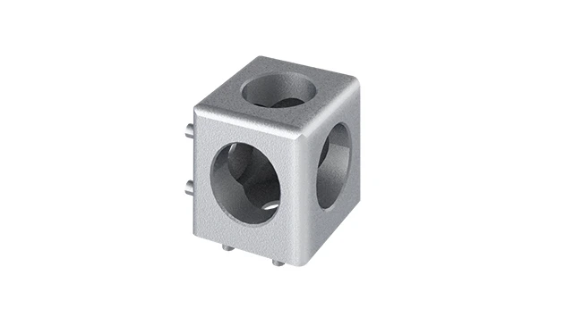
Walk into any modern factory, warehouse, or assembly line, and you'll likely spot structures built with aluminum profiles—workbenches, material racks, conveyor supports, and more. These systems rely on a hidden hero: the connectors that hold everything together. Among the most critical of these are aluminum profile 3 way connectors —the unsung components that join three aluminum profile sections at once, enabling the creation of stable, multi-directional structures. But here's the thing: not all connectors are created equal. A weak 3 way connector can turn a sturdy workbench into a wobbly hazard, or a reliable material rack into a collapse risk. That's why testing their strength isn't just a "nice-to-do"—it's essential for safety, efficiency, and cost-effectiveness.
In this guide, we'll break down how to properly test the strength of aluminum profile 3 way connectors, step by step. Whether you're a manufacturer sourcing components, a plant manager overseeing equipment, or a DIY enthusiast building a custom setup, these tests will help you ensure your connectors can handle real-world demands. We'll cover everything from visual inspections to mechanical stress tests, and even share insights on common pitfalls to avoid. Let's dive in.
Why Testing Aluminum Profile 3 Way Connectors Matters
Before we get into the "how," let's talk about the "why." Aluminum profiles and their accessories—like 3 way connectors—are the backbone of lean manufacturing systems, modular workstations, and automated production lines. Think about a typical scenario: a material rack B (3 row and 3 floor) loaded with heavy components, or a workbench supporting precision tools and assemblies. Every time an operator places a load on that structure, the 3 way connectors absorb stress from multiple directions. If they fail, the consequences range from minor delays to major accidents.
Consider a small electronics factory that skipped connector testing. They installed a new assembly line with aluminum profile workstations, using 3 way connectors to join the frame. Within weeks, operators noticed the workbench shaking during use. One day, a shelf holding circuit boards collapsed, damaging inventory and halting production for hours. An investigation revealed the connectors had sheared under the weight—they looked sturdy but couldn't handle the lateral stress of daily operation. The cost of repairs, lost inventory, and downtime far exceeded the time they would have spent testing the connectors upfront.
Testing isn't just about avoiding disasters, though. It also ensures consistency. If you're a supplier or manufacturer, consistent connector strength means you can guarantee performance to clients. For end-users, it means knowing your structures will last, reducing the need for frequent replacements. In short, testing 3 way connectors is an investment in reliability.
Key Properties to Test in 3 Way Connectors
Aluminum profile 3 way connectors are designed to withstand three types of stress: tensile (pulling), shear (sliding), and bending (flexing). Each of these forces acts on the connector differently, so we need to test for all three. Let's break down what each property means:
- Tensile Strength: The maximum force the connector can withstand when being pulled apart along its axis. For example, if a vertical profile is pulled upward while the horizontal profiles are fixed, the connector must resist that pull.
- Shear Strength: The ability to resist forces that try to slide the connected profiles past each other. Imagine a shelf loaded with boxes—the weight pushes horizontally against the connector, trying to shear it off the vertical profile.
- Bending Strength: The connector's resistance to flexing or warping under load. This is critical in structures like cantilever racks, where one end of a profile is unsupported, putting bending stress on the connector.
Additionally, we need to check for durability (how well the connector holds up over repeated use) and fit precision (how snugly it attaches to the aluminum profile, since loose fits reduce strength). Now, let's walk through how to test each of these.

Step 1: Visual Inspection – The First Line of Defense
You don't need fancy equipment to start testing—your eyes are your first tool. A thorough visual inspection can reveal obvious flaws that would fail under stress. Here's what to look for:
Check for Manufacturing Defects
Examine the connector for cracks, dents, or uneven surfaces. Even small cracks in the metal (especially around the screw holes or joint points) can weaken the connector significantly. For example, a hairline crack near the thread of a 3 way connector might seem minor, but when you tighten a bolt, that crack can spread, leading to sudden failure.
Verify Fit with Aluminum Profiles
3 way connectors are designed to fit specific aluminum profile sizes (e.g., 2020, 3030, 4040). A connector that's too loose will wobble, while one that's too tight might damage the profile's T-slot or strip threads when installed. To test fit:
- Slide the connector onto the end of an aluminum profile (without tightening bolts).
- Gently shake the profile—there should be minimal play (no more than 0.5mm of movement).
- Try tightening the connector's bolts to the manufacturer's recommended torque (usually 2-3 Nm for M5 bolts). The connector should grip the profile firmly without distorting it.
Inspect Threads and Fasteners
Most 3 way connectors use set screws or bolts to lock onto the profile's T-slot. Check that the threads in the connector are clean, undamaged, and properly aligned. Cross-threaded or stripped threads will prevent the bolt from securing the connector, leading to slippage under load. If the connector comes with pre-installed bolts, ensure they're made of high-quality steel (look for markings like "8.8" or "10.9" indicating tensile strength).

Step 2: Mechanical Strength Testing – Putting Connectors to the Test
Visual checks are important, but they can't tell you how a connector performs under stress. For that, you need mechanical tests. These require some equipment, but many can be done with basic tools or by partnering with a testing lab. Let's cover the three key tests:
Tensile Strength Test
This test measures how much pulling force the connector can handle before breaking or deforming. Here's how to set it up:
- Setup: Mount two aluminum profiles horizontally, parallel to each other, and use the 3 way connector to attach a third vertical profile between them (forming a "T" shape). Secure the horizontal profiles to a stable base (like a workbench) using clamps.
- Apply Force: Attach a pulley system or a force gauge to the top of the vertical profile. Gradually apply upward force, increasing in 50N increments, and record the force at which the connector starts to slip or deform.
- Pass/Fail: Most industrial-grade 3 way connectors should withstand at least 500-800N of tensile force (depending on size). If the connector slips before reaching this range, it's too weak.
Shear Strength Test
Shear tests simulate the sideways force a connector might experience when a load is applied perpendicular to the profiles. For example, a shelf loaded with boxes exerts shear force on the connectors holding it to the vertical frame.
- Setup: Attach one end of a horizontal aluminum profile to a vertical profile using the 3 way connector. Secure the vertical profile to a rigid surface. The horizontal profile should extend outward, unsupported, like a cantilever.
- Apply Force: Hang weights from the end of the horizontal profile (start with 5kg, then add 2kg increments) or use a hydraulic press to push sideways at the midpoint of the horizontal profile. Record when the connector bends, slips, or detaches.
- Pass/Fail: A good 3 way connector should handle 20-30kg of shear load without permanent deformation. For heavy-duty applications (like material racks), aim for 50kg or more.
Bending Strength Test
Bending tests check if the connector can resist flexing when the connected profiles are bent. This is critical for structures like workbench legs or conveyor supports, which often bend slightly under load.
- Setup: Create a simple frame with three profiles: two vertical (fixed to the ground) and one horizontal, connected by 3 way connectors at the top of each vertical profile. The horizontal profile should span the two verticals, like a beam.
- Apply Force: Place a weight in the center of the horizontal profile (start with 10kg, increasing by 5kg). Use a ruler to measure deflection (how much the horizontal profile sags). Stop when the connector itself starts to bend or the deflection exceeds 10mm (for a 1m span).
- Pass/Fail: The connector should not bend permanently, and the total deflection should return to near-zero when the weight is removed. If the connector warps or the deflection doesn't reset, it's failed.
Step 3: Environmental Testing – Ensuring Longevity
Aluminum profile systems often operate in harsh environments—factories with high humidity, warehouses with temperature fluctuations, or even outdoor settings. To ensure 3 way connectors last, you need to test their resistance to corrosion and temperature extremes.
Corrosion Resistance Test
Aluminum connectors are often anodized or coated to resist rust, but low-quality connectors may have thin or uneven coatings. Here's a simple test:
- Fill a spray bottle with a 5% saltwater solution (simulating humidity or industrial moisture).
- Spray the connector thoroughly, then place it in a sealed plastic bag with a damp sponge (to keep humidity high).
- Leave it for 72 hours, then inspect for white rust (aluminum oxide) or pitting. A quality connector should show no visible corrosion.
Temperature Cycle Test
Temperature changes can cause metal to expand and contract, weakening connectors over time. Test this by:
- Placing the connector in a freezer (-10°C) for 4 hours.
- Immediately transferring it to an oven (60°C) for another 4 hours.
- Repeating this cycle 10 times, then performing a tensile strength test again. The connector should retain at least 90% of its original strength.
Step 4: Load Testing – Simulating Real-World Use
Laboratory tests are useful, but nothing beats simulating how the connector will perform in your actual setup. Load testing involves building a full-scale structure (like a workbench or material rack) and subjecting it to the maximum load it will encounter in daily use—plus a safety margin.
For example, if you're building a workbench E (single deck-without caster) that will hold 150kg of tools and materials, load test it with 225kg (150% of the intended load) for 24 hours. Check the 3 way connectors for signs of stress: cracks, loose bolts, or misalignment. If the structure holds without issues, the connectors are up to the task.
Pro tip: Use a load cell or strain gauge to measure the actual force on the connectors during the test. This gives you precise data on how much stress they're under, helping you confirm they're within safe limits.
Common Mistakes to Avoid When Testing
Even with the best intentions, testing can go wrong if you skip steps or cut corners. Here are some common mistakes to watch for:
- Using Uncalibrated Tools: A force gauge or torque wrench that's out of calibration can give false readings. Always calibrate tools before testing (most should be calibrated annually).
- Testing Only One Connector: Don't assume one good connector means all are good. Test a sample of 5-10 connectors from the same batch—manufacturing inconsistencies can lead to weak units.
- Ignoring Torque Specifications: Over-tightening bolts can strip threads or crack the connector; under-tightening leads to slippage. Always follow the manufacturer's torque guidelines (usually printed on the connector or in the datasheet).
- Neglecting Repeated Stress: A connector might pass a single load test but fail after repeated use. For high-cycle applications (like conveyor systems), perform a fatigue test: apply 50% of the maximum load, then repeat 10,000 times. If it holds, it's durable.
Comparing Test Methods: A Quick Reference Table
| Test Type | Tools Needed | Purpose | Pass Criteria |
|---|---|---|---|
| Visual Inspection | Eye, flashlight, ruler | Check for defects, fit, and thread quality | No cracks, snug fit, undamaged threads |
| Tensile Strength | Force gauge, pulley system | Resistance to pulling forces | Withstands 500-800N without slipping |
| Shear Strength | Weights, hydraulic press | Resistance to sideways force | Handles 20-50kg without deformation |
| Environmental (Corrosion) | Saltwater, plastic bag | Resistance to rust/moisture | No corrosion after 72 hours |
| Load Testing | Weights, load cell | Real-world performance | Holds 150% of intended load for 24 hours |
Conclusion: Invest in Strength, Avoid Downtime
Testing the strength of aluminum profile 3 way connectors might seem like extra work, but it's a small price to pay for peace of mind. A weak connector can lead to failed equipment, injured workers, and costly delays—none of which any business can afford. By following these steps—visual inspection, mechanical testing, environmental checks, and load simulation—you can ensure your connectors are up to the task.
Remember, the goal isn't just to "pass" the tests, but to build structures that last. Whether you're using aluminum profile accessories in a factory, a warehouse, or a workshop, strong connectors are the foundation of a reliable system. So take the time to test—your team, your bottom line, and your sanity will thank you.