- Company Articles
- Products and Technology
- Product knowledge
- Load-Bearing Calculation for 4040F EU Standard Aluminum Profile Structures

Load-Bearing Calculation for 4040F EU Standard Aluminum Profile Structures
Related Product
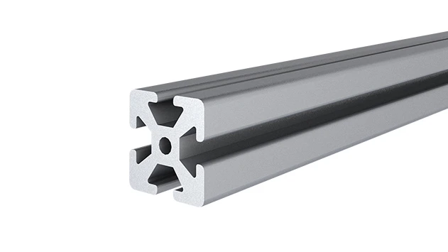
4040F EU Standard Aluminum Profile
4040F is a 4.00x4.00 CM fractional 40 series square extrusion T-slot profile with four side open T-slots, each side with 4.00cm face. The profile has align-a-grooves to assist in aligning connecting profiles.
Why Load-Bearing Calculation Matters More Than You Think
Let's start with a scenario we've all heard of (or maybe even experienced): A workbench in a busy factory suddenly sags under the weight of tools and materials, causing a delay in production. Or a material rack, stacked with components, wobbles dangerously because the supports can't handle the load. These aren't just minor inconveniences—they're safety hazards, efficiency killers, and costly mistakes. And more often than not, they trace back to one critical oversight: skipping or miscalculating the load-bearing capacity of the structures, especially when using versatile but precision-dependent materials like the 4040F EU standard aluminum profile.
If you're in manufacturing, warehousing, or any industry that relies on custom workstations, material racks, or lean production setups, the 4040F aluminum profile is probably a familiar sight. Its 40x40mm cross-section, lightweight yet sturdy build, and compatibility with a wide range of aluminum profile accessories make it a go-to choice for everything from simple workbenches to complex conveyor systems. But here's the thing: its versatility can sometimes lull us into overconfidence. Just because it *looks* strong doesn't mean it can handle every load you throw at it—especially if you don't account for factors like span length, support spacing, or the quality of the joints holding it all together.
In this article, we're going to break down the art and science of load-bearing calculation for 4040F structures. We'll skip the overly technical jargon (no engineering degree required, promise) and focus on practical insights you can apply directly to your projects. Whether you're building a workbench for your workshop, designing a material rack for a warehouse, or partnering with a lean system supplier to optimize your production line, understanding how to calculate and maximize load capacity will save you time, money, and headaches down the line.
First Things First: What Even Is a 4040F EU Standard Aluminum Profile?
Before we dive into calculations, let's make sure we're all on the same page about what the 4040F profile actually is. The "4040" part is straightforward: it refers to the profile's cross-sectional dimensions, measuring 40mm in width and 40mm in height. The "F" suffix, specific to EU standards, denotes a particular groove design—typically featuring T-slots along all four sides, which makes it easy to attach aluminum profile accessories like brackets, panels, and connectors. This design is a game-changer for flexibility: you can reconfigure structures on the fly without welding, just by sliding in bolts or clips into those T-slots.
But what really sets the 4040F apart is its manufacturing process. Like most high-quality aluminum profiles, it's made using aluminum extrusion—a method where heated aluminum billets are pushed through a die to create the desired shape. This process ensures consistent wall thickness, precise dimensions, and a smooth surface finish. The material itself is usually 6063-T5 aluminum alloy, known for its excellent balance of strength, corrosion resistance, and machinability. For the 4040F, the wall thickness typically ranges from 1.5mm to 3mm, depending on the manufacturer, and this thickness is a key variable in load-bearing capacity (more on that later).
Think of it as the "building block" of modern industrial structures. A lean system supplier, for example, might use 4040F profiles to build modular workstations that adapt to changing production needs. A workshop might use them to construct a heavy-duty workbench that holds power tools, while a warehouse could rely on them for sturdy material racks. But in all these cases, the profile's ability to bear weight safely depends on how it's designed, supported, and connected—starting with the basics of load calculation.

Key Factors That Make or Break Load-Bearing Capacity
Load-bearing capacity isn't just about the profile itself—it's a puzzle with multiple pieces. Even the strongest 4040F profile will fail if you ignore one of these critical factors. Let's break them down in plain language:
1. Span Length: The Distance Between Supports
Imagine holding a ruler at both ends: it's stiff and can support a small weight. Now hold it by one end only, and it bends easily. The same logic applies to aluminum profiles. The "span length"—the distance between two supports (like the legs of a workbench or the uprights of a rack)—is the single biggest factor in how much weight a profile can carry. The longer the span, the less weight it can handle before bending or deflecting excessively. For example, a 4040F profile with a 500mm span might support 50kg, but stretch that span to 1500mm, and the max load could drop to 10kg or less.2. Support Configuration: Fixed, Pinned, or Cantilevered?
How you anchor the profile also matters. A profile fixed rigidly at both ends (like a workbench beam bolted to two legs) will handle more weight than one that's only pinned (allowed to rotate slightly at the supports) or cantilevered (supported at one end, with the other end hanging free). Fixed supports prevent both vertical movement and rotation, distributing the load more evenly. Cantilevered setups, while useful for overhangs, are the weakest and require extra caution.3. Connections: Aluminum Profile Accessories Make All the Difference
You could have the thickest 4040F profile on the market, but if you skimp on aluminum profile accessories—like joints, brackets, or end caps—your structure will still fail. Connections are the "weak links" in the chain. A loose joint or a flimsy bracket can turn a rigid structure into a wobbly mess under load. For example, using low-quality plastic connectors instead of reinforced aluminum joints might save a few dollars upfront, but they'll stretch or crack under stress, reducing the overall load capacity. Even something as simple as overtightening a bolt (stripping the thread) or undertightening (allowing movement) can compromise the connection.4. Material Thickness and Profile Design
Not all 4040F profiles are created equal. A profile with a 3mm wall thickness will naturally support more weight than one with a 1.5mm wall, assuming all other factors are the same. Additionally, some 4040F variants have reinforced internal ribs or T-slot designs that add rigidity. Always check the manufacturer's specs for wall thickness and section modulus (a measure of a profile's resistance to bending).5. Load Distribution: Uniform vs. Point Loads
Is the weight spread evenly across the profile (like a stack of boxes on a shelf) or concentrated in one spot (like a heavy machine on a workbench)? Uniform loads are easier on the profile because the stress is distributed. Point loads, on the other hand, create higher stress at the point of contact, increasing the risk of bending or failure. For example, a 20kg tool sitting in the middle of a workbench beam will stress the profile more than 20kg of evenly spread materials.Crunching the Numbers: A Practical Guide to Load-Bearing Calculation
Okay, let's get a bit technical—but don't worry, we'll keep the math simple. Load-bearing calculation for aluminum profiles boils down to two key checks:
bending stress
(will the profile break?) and
deflection
(will it bend too much, even if it doesn't break?).
Bending Stress: Avoiding Breakage
When a profile bends under load, it experiences "bending stress" on its outer fibers. The goal is to ensure this stress stays below the profile's yield strength (the point where it permanently deforms). The formula is:σ = (M * c) / I
Where:- σ = Bending stress (in MPa)
- M = Maximum bending moment (in N·mm)
- c = Distance from the neutral axis to the outer fiber (half the profile height, so 20mm for 4040F)
- I = Moment of inertia (a measure of the profile's resistance to bending, provided by the manufacturer)
Deflection: Avoiding Excessive Bending
Even if the stress is within safe limits, too much deflection (bending) can be a problem. A workbench that sags 20mm under load might not break, but it's unstable for precision work. The general rule is deflection should be less than L/200 (for static loads) or L/300 (for dynamic loads like moving materials). For a 1000mm span, that's 5mm or 3.3mm max deflection. The deflection formula for a uniformly loaded fixed-end beam is:δ = (W * L⁴) / (384 * E * I)
Where E = Young's modulus of aluminum (~69,000 MPa). Using our earlier example (W=80kg=784N, L=1000mm, I=12,000 mm⁴): δ = (784 * 1000⁴) / (384 * 69,000 * 12,000) ≈ 2.5mm, which is under the L/200 limit (5mm). Good to go!A Quick Reference Table: 4040F Load Capacities for Common Spans
To make this easier, here's a simplified table showing approximate max uniform loads for a 4040F profile (2mm wall, fixed at both ends, with a 50% safety factor). Always check with your aluminum profile supplier for exact specs!| Span Length (mm) | Max Uniform Load (kg) | Notes |
|---|---|---|
| 500 | 120–150 | Suitable for heavy workbench tops with tools |
| 1000 | 30–40 | Good for light material racks or workbench beams |
| 1500 | 10–15 | Only for lightweight applications (e.g., cable trays) |
| 2000 | 5–8 | Use only with additional supports |
Note: These values assume 2mm wall thickness, fixed-end supports, and uniform loading. Point loads (e.g., a single heavy tool) will reduce max load by ~50%.
Real-World Applications: From Workbenches to Lean Production Lines
Let's ground this in practical use cases. The 4040F profile isn't just a theoretical material—it's the backbone of structures you interact with daily. Here are two common scenarios where load-bearing calculations turn into real-world success (or failure):
Workbench E (Single Deck–Without Caster): A Case Study
Workbench E is a popular model in many factories: a single-deck surface supported by 4040F legs and crossbeams, no casters (so it's fixed in place). The surface needs to hold tools, parts bins, and maybe a small assembly project—let's say a total load of 60kg. The crossbeams (the 4040F profiles running front-to-back under the deck) have a span of 800mm (distance between the legs). Using our earlier table, an 800mm span for 4040F (2mm wall) can handle ~50kg per beam. If we use two crossbeams, that's 100kg total capacity—plenty for 60kg, even with a safety factor. But if we skimp and use only one crossbeam, the span increases to 1200mm (distance between the front and back legs), dropping capacity to ~20kg. Suddenly, 60kg is way too much, and the bench sags. Moral of the story: crossbeams and span length matter more than you might think.Material Rack B (3 Row and 3 Floor): When Racks Meet Reality
Material Rack B is a 3-row, 3-floor storage system, often used in warehouses to organize small parts. Each floor uses 4040F profiles as the supporting beams, with a span of 1200mm between uprights. The warehouse manager wants to load each floor with 15kg boxes, 10 boxes per floor (150kg total). Using our earlier formula, a 1200mm span for 4040F (2mm wall) has a max uniform load of ~25kg per beam. If each floor has 4 supporting beams, total capacity is 4 * 25kg = 100kg—less than the 150kg needed. The solution? Either add more beams (reducing span per beam) or upgrade to a thicker-walled 4040F (3mm walls, which might boost capacity to 40kg per beam, giving 160kg total). A lean system supplier would likely recommend the latter, as it avoids overcomplicating the design with extra beams.Lean System Setups: Flexibility + Strength
A lean system supplier specializes in creating efficient, adaptable workspaces. For example, they might design a production line where workstations can be reconfigured as orders change. Here, 4040F profiles shine—they're lightweight enough to move but strong enough to support tools and materials. But to keep the system "lean," they can't overbuild (wasting materials) or underbuild (risking failure). Load calculations ensure each workstation is optimized: a assembly station with a 800mm span might use 2mm wall profiles, while a testing station with heavier equipment uses 3mm walls. Aluminum profile accessories like quick-connect joints let them reconfigure spans on the fly, but only if they know the load limits for each setup.Common Mistakes (and How to Avoid Them)
Even with the best intentions, it's easy to slip up. Here are the most frequent errors we see, and how to steer clear:
Mistake #1: Ignoring Aluminum Profile Accessories
It's tempting to focus only on the profile and forget the joints, brackets, and end caps. But a joint that can't handle tension or shear forces will fail before the profile does. For example, using plastic T-slot nuts instead of metal ones might save money, but they'll strip under heavy loads, causing the structure to loosen. Always check the load ratings of accessories—your aluminum profile supplier should provide specs for joints and brackets, too.Mistake #2: Overestimating "Real-World" Loads
You calculate the max load as 50kg, so you load it with 50kg. But in reality, loads are rarely "uniform." A worker might set a 20kg tool in one spot (a point load), or someone might lean on the structure, adding extra stress. Always add a 30–50% safety factor to your calculated max load. If the math says 50kg, aim for 30kg in practice.Mistake #3: Forgetting Deflection in Dynamic Loads
Static loads (like a box sitting still) are one thing; dynamic loads (like a box being slid onto a rack) are another. Dynamic loads create impact, increasing deflection. If your calculation assumes static load but the application is dynamic (e.g., a conveyor using 4040F rails), you'll need to multiply the load by 1.5–2x to account for impact.The Fix: Partner with a Knowledgeable Supplier
You don't have to do this alone. A reputable aluminum profile supplier or lean system supplier will have engineering resources to help with calculations. They can provide custom specs, test samples, and even recommend accessory combinations that boost load capacity. It's worth the conversation—your safety and efficiency depend on it.Wrapping Up: Strong Structures Start with Smart Calculations
The 4040F EU standard aluminum profile is a workhorse, but it's not a magic solution. Its load-bearing capacity depends on careful planning: span length, supports, connections, and material specs all play a role. Whether you're building a workbench, a material rack, or a lean production line, taking the time to calculate load capacity isn't just about avoiding failures—it's about building structures that are efficient, safe, and adaptable.
Remember: the next time you see a sturdy aluminum structure, behind it is someone who asked the right questions: How long is the span? What's the load distribution? Are the accessories up to the task? By asking those questions yourself, you'll join the ranks of professionals who build structures that stand the test of time. And if you ever need help, don't hesitate to reach out to your aluminum profile supplier—they're there to ensure your project succeeds, from calculation to installation.