- Company Articles
- Products and Technology
- Product knowledge
- 3D Modeling 4080B EU Standard Aluminum Profile Structures: Software & Best Practices

3D Modeling 4080B EU Standard Aluminum Profile Structures: Software & Best Practices
Related Product
4080B EU Standard Aluminum Profile
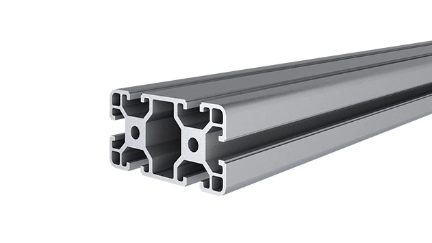
4080B is a 4.00x8.00 CM fractional 40 series square extrusion T-slot profile with two side open T-slots, each side with 4.00cm face, two side with 8.00cm face. The profile has align-a-grooves to assist in aligning connecting profiles.
Walk into any modern factory, workshop, or even a tech startup's lab, and you'll likely spot the unsung heroes of industrial design: aluminum profiles. These modular, versatile structures form the backbone of workbenches, material racks, assembly lines, and more. Among the most widely used is the 4080B EU standard aluminum profile—a workhorse known for its strength, precision, and adaptability. But designing with these profiles isn't just about slapping pipes together; it requires careful planning, especially when scaling from a sketch to a functional, durable structure. That's where 3D modeling comes in. In this guide, we'll dive into how to effectively 3D model 4080B aluminum profile structures, the software tools that make the process smoother, and the best practices that ensure your designs are not just functional, but optimized for real-world use.
Understanding the 4080B EU Standard Aluminum Profile
Before we jump into modeling, let's get familiar with the star of the show: the 4080B EU standard aluminum profile. What makes it so popular? For starters, its dimensions: 40mm in width and 80mm in height, with a standardized T-slot design that runs along its length. These slots are the secret to its flexibility—they let you attach accessories like brackets, panels, and guides without welding or drilling, making customization a breeze. Whether you're building a heavy-duty workbench or a lightweight material rack, the 4080B's aluminum extrusion profile (typically made from 6063-T5 aluminum) offers the perfect balance of strength and weight, with excellent corrosion resistance to boot.
But here's the thing: the profile itself is just the starting point. To build a complete structure, you'll need aluminum profile accessories—think end caps to protect edges, corner brackets for right-angle joins, and aluminum profile joints to connect multiple profiles at different angles. These accessories turn a single length of aluminum into a modular system, but only if they're modeled correctly. A misaligned joint or a miscalculated slot position can throw off the entire assembly, leading to wobbly workbenches or inefficient material flow. That's why 3D modeling isn't a luxury here; it's a necessity.
Key Software Tools for 3D Modeling Aluminum Profile Structures
Not all 3D modeling tools are created equal, especially when it comes to aluminum profiles. Some excel at detailed mechanical design, others at collaboration, and a few are even built specifically for modular systems like T-slot profiles. Let's break down the top contenders and when to use them.
| Software | Best For | Standout Features for Aluminum Profiles | Learning Curve |
|---|---|---|---|
| SolidWorks | Detailed mechanical design & engineering validation | Extensive library of standard parts (including 4080B profiles); robust simulation tools for stress testing. | Moderate to advanced |
| Fusion 360 | Cloud-based collaboration & rapid prototyping | Parametric modeling (easy to adjust dimensions); built-in access to manufacturer-specific accessory libraries. | Beginner to moderate |
| AluPro | Specialized aluminum profile design | Pre-loaded with EU standard profiles (4080B included); drag-and-drop accessory placement; auto-generates BOMs. | Beginner-friendly |
| AutoCAD | 2D drafting with 3D capabilities | Precision drafting tools; compatible with most manufacturer CAD files for profiles and accessories. | Moderate |
For most users, Fusion 360 strikes a great balance. Its parametric approach means if you need to tweak the length of a 4080B profile or swap out an aluminum profile joint, the entire model updates automatically—no manual redrawing required. AluPro, on the other hand, is a niche gem; it's like having a digital hardware store at your fingertips, with every 4080B profile, aluminum guide rail, and caster wheel pre-modeled to EU standards. If you're new to 3D modeling, starting with AluPro can save hours of frustration.

Best Practices for 3D Modeling 4080B Structures
Even with the right software, modeling aluminum profiles can go off the rails without a clear process. Here are the best practices that will keep your designs accurate, efficient, and ready for manufacturing.
1. Start with Accurate Dimensions (and Stick to Them)
The 4080B profile is defined by strict EU standards, so there's no room for guesswork. Always use the manufacturer's official CAD files or dimension specs for your 3D model. This includes not just the profile's width and height, but also the T-slot dimensions (slot width, depth, spacing) and wall thickness. A common mistake? Assuming all 40mm x 80mm profiles are identical—minor variations in slot design can mean an accessory from one supplier won't fit another's profile. Most suppliers (like Bosch Rexroth or Item) offer free CAD downloads for their 4080B profiles; use them. Your future self (and your assembly team) will thank you.
2. Model Accessories as They Actually Fit
Aluminum profile accessories are the glue that holds your structure together, so don't treat them as an afterthought. When adding an aluminum profile joint, for example, model how it interacts with the T-slot: does it use a bolt and nut? A spring-loaded pin? How much clearance does it need to rotate or lock in place? The same goes for aluminum guide rail A or B—these are often used to guide rollers or sliding components, so their position relative to the profile's slot directly affects functionality. In Fusion 360 or SolidWorks, you can use "mate" or "constraint" tools to simulate how accessories attach, ensuring there's no interference or slack in the final design.
Pro tip: Group accessories into sub-assemblies. If you're designing a workbench with a shelf, caster wheels, and a tool rail, model each of these as separate sub-assemblies. This makes it easier to swap out components (e.g., upgrading from fixed casters to swivel ones) without disrupting the entire model.
3. Simulate Real-World Loads and Movements
A workbench might look sturdy on screen, but will it hold 200kg of equipment without bending? A material rack with three shelves sounds practical, but will the 4080B profiles sag under the weight of stacked boxes? 3D modeling software lets you answer these questions before you cut a single piece of aluminum. Use simulation tools to test stress, strain, and deflection: apply loads to shelves, check how joints handle torque, and even simulate vibrations if the structure will be near machinery.
For example, if you're designing a material rack B (3 row and 3 floor) using 4080B profiles, simulate the weight of materials on each shelf. If the middle shelf sags beyond the acceptable limit (typically 2-3mm for industrial racks), you might need to add cross-braces or switch to a thicker-walled profile. Software like SolidWorks has built-in finite element analysis (FEA) tools for this, while Fusion 360 offers generative design to suggest optimized support structures—saving you time and material costs.
4. Collaborate with Your Team (and Suppliers)
3D modeling isn't a solo sport. Share your model with the assembly team early—they'll spot issues you might miss, like hard-to-reach bolts or awkward joint placements. If you're working with a supplier, send them the 3D file (in a universal format like STEP or STL) to confirm that the accessories you've specified are in stock and compatible with their 4080B profiles. Cloud-based tools like Fusion 360 make this easy: multiple users can comment on the model in real time, and you can track changes to avoid version confusion.
5. Generate a Detailed Bill of Materials (BOM)
Once your model is finalized, don't just export a 3D file—generate a BOM. This list of parts (profiles, joints, casters, etc.) should include quantities, part numbers, and supplier info. Tools like AluPro auto-generate BOMs as you design, but even in SolidWorks or Fusion 360, you can customize BOM templates to include critical details. A clear BOM prevents ordering mistakes (like forgetting end caps for exposed profile ends) and speeds up assembly, as the team knows exactly what parts to pick from the inventory.
Case Study: Designing a Heavy-Duty Workbench with 4080B Profiles
The Goal: Create a workbench for an electronics assembly line that needs to support tools, a soldering station, and a small parts bin, with casters for mobility.
The Process: The design team started with a sketch, then imported the 4080B profile CAD file into Fusion 360. They modeled the frame using 4080B vertical supports and horizontal rails, adding aluminum profile joints at each corner for stability. For the worktop, they used a 25mm aluminum honeycomb panel (attached via T-slot brackets) and added aluminum guide rail A along the back edge to hold tools. Casters with brake locks were mounted to the base using castor fixed plates, and simulation tests confirmed the structure could hold 300kg without deflection.
The Result: The 3D model caught two issues early: the initial caster placement made the bench wobbly (fixed by moving them to the corners), and the tool rail was too high for comfortable access (lowered by 50mm). The final design was assembled in 2 hours (down from the estimated 4 hours with a 2D drawing), and the BOM ensured all parts arrived on time.
Common Pitfalls to Avoid
Even with best practices, it's easy to stumble. Here are the mistakes designers often make when modeling 4080B structures—and how to steer clear:
- Ignoring T-slot tolerances: T-slots have slight manufacturing tolerances (usually ±0.1mm). If you model a joint to fit "perfectly" on paper, it might bind in real life. Add 0.1-0.2mm of clearance in your model.
- Overlooking weight distribution: A top-heavy structure (like a workbench with heavy tools on the top shelf) will tip easily. Use simulation to check the center of gravity and add a wider base if needed.
- Using generic accessories: Not all "4080B compatible" accessories are created equal. Stick to accessories from the same supplier as your profiles, or verify compatibility with their CAD files.
Conclusion: From Screen to Shop Floor
Designing with 4080B EU standard aluminum profiles is a blend of art and science. The profile's versatility makes it ideal for endless applications, but unlocking that potential requires precision—precision that 3D modeling delivers. By choosing the right software, following best practices (accurate dimensions, detailed accessory modeling, simulation, collaboration), and avoiding common pitfalls, you'll create structures that are not just functional, but efficient, durable, and easy to assemble.
So the next time you sketch a workbench or material rack, remember: the 3D model isn't just a tool—it's your bridge from idea to reality. With the 4080B profile as your canvas and these practices as your guide, you'll build structures that stand the test of time (and the chaos of the shop floor).