- Company Articles
- Products and Technology
- Installation And Maintenance
- Troubleshooting Common Issues with Aluminum Guide Rail A Installation

Troubleshooting Common Issues with Aluminum Guide Rail A Installation
Related Product
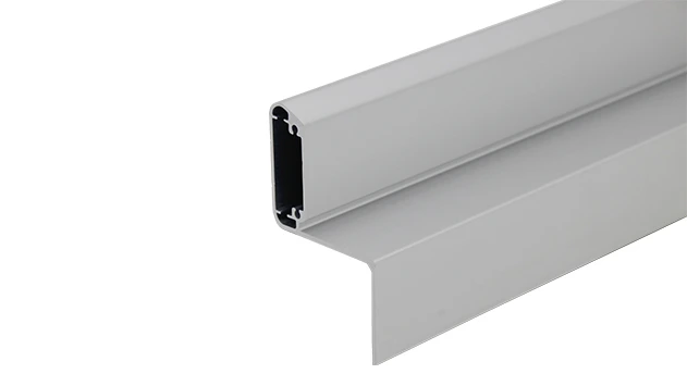
Aluminum Guide Rail A
The aluminum guide rails hold the transport goods securely on the roller track. For installation, the guide rails are simply pushed over the roller tracks.To protect sensitive products.
Troubleshooting Common Issues with Aluminum Guide Rail A Installation
When you're on the factory floor, surrounded by the hum of machinery and the steady flow of materials, the last thing you need is a hiccup in your production line. Aluminum Guide Rail A, a workhorse in lean manufacturing setups, often takes center stage in keeping things moving—whether it's guiding components along a flow rack, supporting a conveyor system, or structuring a flexible workstation. But even the most reliable components can throw curveballs during installation. Let's walk through the nitty-gritty of solving the most frustrating problems you might face, so you can get your line up and running smoothly again.
Why Aluminum Guide Rail A Matters in Your Lean System
Before diving into troubleshooting, let's take a moment to appreciate why this guide rail is such a big deal. As a key part of your lean pipe system, Aluminum Guide Rail A isn't just a metal bar—it's the backbone of efficiency. It works hand-in-hand with aluminum profile and aluminum pipe accessories to ensure materials glide seamlessly, reduce downtime, and keep your team focused on what they do best: building quality products. When installed right, it's quiet, durable, and almost invisible in its reliability. But when things go wrong? Suddenly, that "invisible" component becomes a major headache.
Common Installation Headaches (and How to Fix Them)
Let's roll up our sleeves and tackle the issues that make installers sigh, supervisors frown, and production schedules slip. We'll break down each problem with the symptoms you'll notice, why they happen, and step-by-step fixes that actually work.
1. Uneven Rail Joints: When "Smooth" Feels Like a Bumpy Road
You've spent hours aligning sections of Aluminum Guide Rail A, but when you run a test with a sample component, it jolts, scrapes, or even gets stuck at the joints. Worse, the noise is enough to make everyone in the area glance over. If you run your hand along the rail, you can feel a tiny (or not-so-tiny) lip where two sections meet.
Why It Happens
More often than not, this boils down to three culprits:
- Measurement Mishaps: Even a 1mm error in cutting or spacing can throw off alignment. When sections aren't cut to exact lengths, joints won't meet flush.
- Mismatched Accessories: Using the wrong roller track placon mount for rail connection is a classic mistake. For example, mixing "flat" mounts with "drop high" mounts (like 40 roller track placon mount drop high vs. flat) creates uneven surfaces.
- Warped Mounting Surfaces: If the aluminum profile or workbench surface itself is bent or uneven, the rail will follow suit—no matter how carefully you install it.
How to Fix It
Let's turn that bumpy joint into a smooth transition:
- Double-Check Measurements: Grab a precision level and tape measure. Re-measure each rail section and mark cutting lines with a square—don't rely on "eyeballing it." For longer runs, use a string line to ensure straightness before securing.
- Verify Accessories: Match the placon mounts to your rail type. Aluminum Guide Rail A often pairs with specific mounts (check the specs sheet!). For example, if you're using 38 aluminum roller track, use the corresponding placon mount designed for that size—mixing 38mm and 40mm parts is a recipe for misalignment.
- Level the Base: If the mounting surface is warped, shim it with thin aluminum strips (0.5mm or 1mm thick) under the low spots. For workbenches, use adjustable leveling feet to tweak the surface until it's perfectly flat before attaching the rail.
- Test Before Final Tightening: Loosely secure the rail sections first, then slide a test component along the entire length. Adjust individual mounts until the component glides without resistance, then fully tighten the screws.
Pro Tip: After installation, apply a thin layer of silicone lubricant to the joint—this reduces friction and masks minor imperfections, making the transition even smoother.
2. Loose Fittings: When Your Rail Starts "Dancing"
A week after installation, you notice the rail is wobbly. (screws) are backing out, and the rail shifts slightly when heavy materials pass over it. In extreme cases, a placon mount might even detach completely—scary stuff when you're dealing with expensive components or fast-moving parts.
Why It Happens
Loose fittings are rarely due to "bad luck"—they're usually a mix of human error and material science:
- Under-Tightened Screws: Using a regular screwdriver instead of a torque wrench means you might not hit the optimal tightness. Too loose, and vibration will loosen them further; too tight, and you risk stripping the threads.
- Missing Lock Washers: Aluminum and plastic accessories can vibrate loose over time. Without lock washers or thread-locking fluid, screws are basically just waiting to back out.
- Thermal Expansion: Factories get hot—really hot. Metal rails expand in heat and contract in cool conditions. Over time, this "breathing" can loosen screws that weren't secured with anti-vibration measures.
How to Fix It
Let's lock those fittings in place for good:
- Use a Torque Wrench: Check the manufacturer's specs for recommended torque (usually 4-6 Nm for aluminum components). A torque wrench ensures you hit the sweet spot—tight enough to stay secure, not so tight you damage the threads.
- Add Locking Mechanisms: Slide a split lock washer onto each screw before tightening. For high-vibration areas (like near conveyor motors), apply a drop of thread-locking fluid (blue, not red—red is permanent!) to the threads. It'll harden slightly, preventing loosening.
- Upgrade to Nylon-insert Nuts: If your setup uses nuts instead of screws, swap standard nuts for nylon-insert lock nuts. The nylon grips the thread, resisting vibration better than metal alone.
- Schedule Regular Checks: Even with the best installation, vibrations happen. Add a monthly "tightness check" to your maintenance routine—focus on high-traffic rails and areas near machinery.
| Accessory Type | Recommended Torque | Locking Method |
|---|---|---|
| Placon Mounts (Rail Connection) | 5 Nm | Split Washer + Thread-Lock |
| Aluminum Profile Brackets | 4 Nm | Nylon-insert Nut |
| End Supports (with Stop) | 6 Nm | Double Nut (Jam Nut) |
3. Sagging Under Load: When Your Rail Can't "Take the Weight"
Everything looks great during testing with light components, but when you load up with full production materials (think heavy 3C assembly parts or medical device components), the rail sags in the middle. (Materials) slow down or even stop, and you notice visible bending in the rail itself.
Why It Happens
This is usually a case of "right part, wrong job" or spacing issues:
- Under-Spec'd Rail: Aluminum Guide Rail A comes in different thicknesses and materials. Using a lightweight mini aluminum roller track for heavy loads (like 20kg+ per component) is like using a bicycle to tow a truck—it'll work… until it doesn't.
- Mount Spacing Too Wide: Placing supports every 120cm instead of the recommended 80cm? The rail can't span that distance without sagging, especially under weight.
- Weak Mounting Points: Attaching the rail to thin or flimsy aluminum profile (like 2020 instead of 3030 or 4040) means the base itself bends, even if the rail is strong.
How to Fix It
Let's give your rail the backbone it needs:
- Check Load Ratings: Refer to the datasheet for Aluminum Guide Rail A. For example, 38 aluminum roller track yellow with wheel flange typically handles 15-20kg per linear meter, while 40 steel roller track can manage 30kg+. If your load exceeds this, upgrade to a heavier rail (like 85 steel roller track for extreme cases).
- Add More Supports: Reduce the distance between placon mounts. Most rails need supports every 60-80cm for heavy loads. For example, if you originally placed mounts at 100cm intervals, add a middle support to split that into 50cm segments—sagging will disappear.
- Upgrade the Base Profile: If the aluminum profile is bending, switch to a thicker or wider profile. 4040 aluminum profile is stronger than 3030, which is stronger than 2020. For extra support, use aluminum honeycomb panel under the rail to distribute weight.
- Reinforce with Cross-Braces: For long rail runs (3m+), add diagonal cross-braces between supports using lean pipe and joints. This prevents lateral movement and adds rigidity.
Real-World Example: A 3C assembly plant was using 38mm aluminum rail with mounts every 100cm for 18kg components. After switching to 40mm steel rail and reducing mount spacing to 70cm, sagging vanished, and production speed increased by 15%—all because materials moved smoothly again.
4. ESD Failures: When Static Becomes a Silent Saboteur
If you're using Aluminum Guide Rail A in ESD-sensitive areas (like electronics manufacturing), you might notice static discharges zapping components or ESD meters reading above the safe threshold ( < 10^9 ohms). Even worse, you might have random product failures that trace back to static damage—costly and frustrating.
Why It Happens
ESD issues with aluminum rails are often overlooked during installation:
- Broken Ground Path: The rail isn't properly grounded to the ESD workbench or floor. Paint, anodization, or dirt on contact points can block conductivity.
- Non-ESD Accessories: Using standard plastic roller track guide rail (yellow or grey) instead of ESD-rated black ones introduces insulative materials that trap static.
- Loose Connections: Even if you grounded the rail initially, loose screws or corroded contacts can break the ground path over time.
How to Fix It
Let's turn that static-prone rail into an ESD-safe zone:
- Use ESD-Rated Components: Swap out standard parts for ESD versions. For example, choose aluminum roller track black esd with side guide instead of yellow or white. These have conductive additives that dissipate static, not trap it.
- Ground the Rail Properly: Connect the rail to the workbench's ESD ground using a braided ground strap (4mm² minimum). Scrape off any anodization or paint at the connection point to ensure metal-to-metal contact, then secure with a star washer to bite into the aluminum.
- Test Continuity: Use a multimeter set to "ohms" to check conductivity from the rail to the ground. Resistance should be between 10^6 and 10^9 ohms—if it's higher, clean the contacts or tighten connections.
- Regular ESD Audits: Add the rail to your weekly ESD checklist. Wipe it down with isopropyl alcohol to remove dirt (which insulates), and re-test continuity to catch issues before they damage products.
The Big Picture: Installation as Part of Your Lean Journey
Fixing these issues isn't just about making your rail work—it's about honoring the "lean" in lean pipe system. Lean manufacturing is all about reducing waste, and nothing wastes time like a rail that jams, sags, or fails. By taking the time to install Aluminum Guide Rail A correctly, you're investing in smoother workflows, happier teams, and products that reach customers faster.
Remember, every minute spent troubleshooting a preventable installation issue is a minute not spent innovating or improving. So grab your level, check those accessories, and make that rail work for you—not against you.
Quick Reference: Common Issues at a Glance
| Problem | Key Symptom | First Fix to Try |
|---|---|---|
| Uneven Joints | (Material jamming) | Check placon mount compatibility |
| Loose Fittings | Rail wobble/shifting | Tighten with torque wrench + lock washers |
| Sagging Under Load | Visible rail bending | Add more supports (80cm max spacing) |
| ESD Failures | Static zaps or product damage | Test ground continuity with multimeter |